It has been said that UL doesn't work for guitar amps. I tend not to listen to what others say, so I have tried it. I tried SE UL, and P-P UL. UL just doesn't sound right when the output stages are pushed into clipping. I have tried it a few times and never got anything that I liked, but your tastes may vary.
Finally someone who knows what he is talking about.
There is a good reason why UL Fender Twins have the poorest resale value.
There was other design changes that had an effect on the sound on top of UL operation that neutered the amps. If they knew then what we know now they may have got it right. Mind you, I have yet to loose faith in our buddy tubelab.Finally someone who knows what he is talking about.
There is a good reason why UL Fender Twins have the poorest resale value.
I'm not surprised the Fender speaker died.
A brand name ain't gonna make up for lack of an adequate wattage rating.
The reason that it died is that I tried the cabinet / speaker combination with several of my amps and a Marshall. I did not like the sound it made with any source, so I decided that it didn't deserve to live, so I hooked up a big amp and blasted it into oblivion. It didn't even put up a good fight. I have tried a Peavey speaker in the cabinet and it sounds better, then I put a Jensen Alnico in which is better, but the cabinet just doesn't rock the way it was designed. It is closed back and ported in an attempt to boost bass, but it is way too boomy. It seems resonant (and rather peaky) at about 120 Hz. Time to jigsaw a hole in the back and plug up the port.
So I'm not ready to write off UL mode for guitar amps......Most think triode mode is too bland for guitar, that is unless you like clean.
I wouldn't write off anything.....If you like it and it doesn't blow up, then build it......Whatever "it" is. I once got a lot of mileage out of sticking two dissimilar output tubes in a heavilly modified Bandmaster, An EL34 and a 6L6GC. Sounds almost normal until cranked, then it goes into uncharted territory.
About 15 years ago I was tinkering with amps. This was while my daughter still lived at home. She played in the high school marching band, also played drums, keyboards, and a bit of guitar. She taught drums and keyboards at a local music school while going to college. Most of her friends that hung out here were armed with musical weapons and there was some kind of racket coming out of the back room nearly every day.
I made amps for several of her friends. I had skywired something together using a pair of 6X9 car speakers and several of us were playing with it. I had a Strat and a Les Paul at the time, and everyone else had some kind of solid body electric (grunge was king then). I was about to blow it up or take it apart when one of the guys asked if he could go home and get his guitar (I didn't even know he had one). He returned with an ES335 (hence the comment in my last post) and the amp sounded magical. At mid volume it sounded crystal clear (a rythym player) and there was no intermodulation to cloud up the chords. As the volume was advanced just into clipping it sounded like Lucille. I sold an amp that I wouldn't play myself. You never know what someone else likes until they hear it. I made several amps based on my "Turbo Champ" design (no two were the same). They all had a triode switch, and several users said that they used them to get distortion at lower volumes.
Same seems to go with blocking distortion. It does not seem to be desirable.
Unless you are Neil Young. He wrote a song (on Trans???) that timed his playing with the "farting out" sound his amp was making. I find that blocking is too unpredictable to be useful at all. I can avoid it on small amps by tweaking the coupling cap, grid bias or grid leak resistor, and the grid stopper resistor. For the big stuff, it's direct coupling to the output stage via a cathode or mosfet follower.
The type of distortion some crave coming from the the power-section seems to be based on a handful of independent factors:
OT saturation and impedance
The old Fenders used a rather small OPT. Saturation could be observed on a scope with a dummy load, while not seen into the Fender speaker due to the resonance peak in speaker impedance. Marshalls tended to use a big enough OPT to avoid saturation. I think that the dissimilar tubes trick worked so well in a Fender because the unbalance at high signal levels due to the different Gm's caused saturation distortion at higher frequencies than normal, only on signal peaks. Beware excessive saturation. The tube current skyrockets as the OPT saturates. This can lead to red plate death!
Operating the amp into a mismatched load is another trick that can be used to change the tone. All the Turbo Champs used a Hammond CSE125 OPT with all the impedance taps on a switch for user control. Beware running a high powered P-P amp into a load that is too high (16 ohms on the 4 ohm tap). When the amp is hammered hard into clipping the voltage at the plates of the output tubes can spike to well beyond the expected twice the B+ voltage. This can lead to an arc over at the tube socket or inside the OPT. Once the arc strikes, it is fueled by the B+ voltage and will not stop until something blows. Anyone remember the exploding fireball Ampeg SVT's of the late 60's.
b) the effects of screen-current in fixed-bias configurations, and the choice of resistors.
Some tubes are way more sensitive to screen resistors than others. The king of screen grid sensitivity is the EL34. The old NOS tubes were well made and the screen grid was aligned with (in the shadow of) the control grid to lower screen current. The new stuff isn't made to these critical specs, and even if it is, it doesn't stay that way long when the amp head is sitting on top of the speaker cabinet. This is the real reason why old Marshalls eat new tubes. Tweaking the screen resistor is yet another knob we have to adjust how and when the output stage transitions into distortion. Smaller resistors cause a later (higher power) and harder "edge" at the risk of early tube death. Larger values cause a earlier, gentler transition. The smaller values are generally preferred by players looking for touch sensitivity (the ability to alter the distortion characteristics by how hard the string is picked). Use at least a 1 watt screen resistor on the EL34 (I use 2 watts on guitar amps).
tube-type and frequency response under overdrive.
The tube type, OPT characteristics, load impedance, and loudspeaker impedance VS frequency are all major influences here. The speaker's characteristics change with the applied power too. Plot the amps frequency response into a dummy load at various power levels using a signal generator. Then plot it again into a speaker under the same generator and amp settings. THe two curves don't resemble each other. I put the speaker out in the garage for this test. Some of my amps are rather loud.
Some other "knobs":
Use a mosfet variable voltage regulator to adjust the screen voltage in the output tubes. Then follow that with a switch to select several different series resistors. This allows the selection of different distortion profiles. You can even make a circuit to cause the screen voltage to drop under high volume situations. This emulates "rectifier sag" and even accentuates it. I used an LDR driven from the cathode of the output tube. It allows a self regulating effect for long sustaining compression.
The Marshall "presence" control shunted negative feedback at the higher frequencies accentuating the harmonic distortion without creating excessive bass boom. I got the dumb blonde idea of sticking a 3 knob tone stack into the negative feedback loop. This made some rather cool sounds (like a wah-wah on roids) but was a bridge too far. I didn't have the time to fully figure it all out but the amp could go unstable at some settings with some speakers. With EL34's it would oscillate madly. Too much phase shift and a crappy OPT.
The whole tweaking the stopper resistor thing that was debated earlier.....I tried using an LDR here too. It doesn't make much difference. 5K ohms.....300K ohms, almost no difference until hard overdrive conditions are met. Now wire the LDR in series with the cathode bypass cap in the preamp stages and you have an expression knob to play with. Drive it with a voltage derived from the output tube cathodes. Use an opamp to adjust the gain and polarity for different effects. You can set it up so that the gain stays constant until a certain cathode voltage is acheived, then the gain increases. This can give extreme touch sensitivity, hit the threshold and the amp just explodes into distortion, stay below it and it is totally tame. Reverse the polarity so the gain drops, and set the threshold low. You can sustain a note forever because the gain increases as the note dies out.
I hear you on this. There is no 'magic bullet' design.
There is so many different "sounds" available today that there is no way that one amp can make everyone happy. You build what you want for yourself, and tweak it until you like it. If that one doesn't make you happy, or you grow tired of it, make another.
And even favorites come and go with mood and developments. A change is as good as a rest.
I started making amps out of old TV sets as a teenager (1960's). Dead TV's all had tubes and they were free, just ride to the county dump. Most of my early amps were Champ clones made with 6BQ6's since they were common and 6V6's weren't. Through the 70's and 80's I still made HiFi and guitar amps.....they just had transistors in them. Fortunately moods do change and Tubelab is just that...tubes....with a bit of sand in supporting roles!
I haven't made many guitar amps since my daughter and her friends all moved away, but that is changing.
The tube type, OPT characteristics, load impedance, and loudspeaker impedance VS frequency are all major influences here. The speaker's characteristics change with the applied power too. Plot the amps frequency response into a dummy load at various power levels using a signal generator. Then plot it again into a speaker under the same generator and amp settings. THe two curves don't resemble each other.
Good use for a NFB switch to see the effect of a speaker on the response of an amplifier. My little 15CW5 powered Champ has a NFB switch and toggling between open loop and closed shows how the speaker impedance effects the frequency response. More output at resonance and more sizzle on the top end without NFB. Some speakers I like it in, some out.
When drawing load lines for push pull amps you use 1/4 the plate to plate impedance. In this case 1.25K. This is what each tube sees on it's side of the output transformer to B+.
Also, plate voltage can reach twice the B+ voltage when the tube on the other side is conducting hard.
To take a step away from the theoretical, I am posting X-Y plots of a 5881 in an actual guitar amp driven by a guitar. Sorry it's not an ultralinear output stage, but I don't expect one to be much different.
...
Note instantaneous plate dissipation can be well over 30 watts, plate voltage easily reaches 800V and can go negative several hundred volts.
This is the kind of stress that a guitar amp puts on it's output tubes.
I'm not happy with what this must imply for screen current, without precautions.
Current ratings are kind of 'absolutes' , as all wire is rated by current handling capability.
This rating cannot be increased.
One encouraging thing here is that apparently a well-made tube
can internally take up to 800v across it without arcing.
Since the 6BG6a has (almost) the same guts as a 6L6GC,
it stands to reason that both tubes can take high voltages,
and that the real reason for the design-center maximum
has to do with arcing and tracing around the octal base.
This problem however can be handled several ways:
(1) Not using 'lead-free' tin solder, which grows 'hair'.
(2) coating the socket terminals and surfaces to prevent tracing.
(3) Drilling into the bakelite base, and spraying in 10,000 volt lacquer to prevent arcing inside the base.
What do you think of number 3?(2) coating the socket terminals and surfaces to prevent tracing.
(3) Drilling into the bakelite base, and spraying in 10,000 volt lacquer to prevent arcing inside the base.
Last edited:
Because of the very high voltage spikes in guitar amps, I use ceramic sockets whenever possible. Drilling bakelite sockets and filling with lacquer could work, but it would take some experimentation to get it right. I would look to see if any ham radio DIYers have tried it. Some of those transmitters have B+ over 1000V.
Excessive screen current is another problem in guitar amps. When the plate voltage dips low during clipping, screen current will climb exponentially. It's very hard to predict screen current and limit dissipation to a safe value, especially since playing style plays a role in how much abuse the tube undergoes. There is no easy answer here. You may find a screen stopper resistor that works for you and another guitar player might burn the tubes up in a week. A design that protects the tubes won't produce as much power as some people expect. This does not mean that it won't sound good, it just might not be as loud.
Excessive screen current is another problem in guitar amps. When the plate voltage dips low during clipping, screen current will climb exponentially. It's very hard to predict screen current and limit dissipation to a safe value, especially since playing style plays a role in how much abuse the tube undergoes. There is no easy answer here. You may find a screen stopper resistor that works for you and another guitar player might burn the tubes up in a week. A design that protects the tubes won't produce as much power as some people expect. This does not mean that it won't sound good, it just might not be as loud.
Because of the very high voltage spikes in guitar amps, I use ceramic sockets whenever possible. Drilling bakelite sockets and filling with lacquer could work, but it would take some experimentation to get it right. I would look to see if any ham radio DIYers have tried it. Some of those transmitters have B+ over 1000V.
I may not be being as clear as I intended here:
What I mean is drilling into the bakelite base of the tube itself,
or even stripping it right off, and coating the wires protruding
from the glass.
Here in this hidden area is where many flashovers can occur,
especially if humidity or dust creeps in.
I believe octal bases can be removed the same way they are installed:
Desoldering all pins simultaneously, then sliding off the bakelite base.
Perhaps mixing up some epoxy might also be effective, after spraying the inside of the base and the shoulders around the pins.
Only the tip of the pins need to be uncovered for re-soldering to the base.
People actually sell replacement bases, so that would be an opportune time for High Voltage treatment.
Replacement Bases
Excessive screen current is another problem in guitar amps. When the plate voltage dips low during clipping, screen current will climb exponentially. It's very hard to predict screen current and limit dissipation to a safe value, especially since playing style plays a role in how much abuse the tube undergoes. There is no easy answer here. You may find a screen stopper resistor that works for you and another guitar player might burn the tubes up in a week. A design that protects the tubes won't produce as much power as some people expect. This does not mean that it won't sound good, it just might not be as loud.
Yes, I'm looking into ways to manage screen current without affecting sound quality.
Not ready to offer anything yet.
Here in this hidden area is where many flashovers can occur, especially if humidity or dust creeps in.
That's exactly where the fireworks often starts, especially here in the land of dust, heat, and humidity. I have autopsied some dead tubes and found that the sharp edges of the pins where they are crimped have rusted. Then crud forms on the rusty edges, add some dust and moisture and you get smoke. If a tube has not carbon tracked yet it can sometimes be fixed with an generous injection of WD-40 through the open hole (pin 6).
I believe octal bases can be removed the same way they are installed: Desoldering all pins simultaneously, then sliding off the bakelite base
There is this brown glue that holds the glass envelope in the base. It almost always turns loose when you don't want it to, but never comes loose when you need it to.
Yes, I'm looking into ways to manage screen current without affecting sound quality.
Anything that affects the screen current will affect the sound, especially in the distortion zone. I have experimented with an adjustable CCS (10M45) feeding a 100 ohm 2 watt resistor in series with the screen pin. Works best on EL34, but every tube is different depending on how well it was made. It makes an adjustable power limiter. I call it the "KRANK" knob. It goes from "mellow" to "meltdown".
I was tinkering with a microprocessor based system to calibrate the bias and KRANK settings whenever tubes are changed, or the user presses the button. I haven't had the time to work on it this year, so it won't be happening any time soon.
That's exactly where the fireworks often starts, especially here in the land of dust, heat, and humidity. I have autopsied some dead tubes and found that the sharp edges of the pins where they are crimped have rusted. Then crud forms on the rusty edges, add some dust and moisture and you get smoke. If a tube has not carbon tracked yet it can sometimes be fixed with an generous injection of WD-40 through the open hole (pin 6).
wow another use for WD-40!
 My friend the repairman swears by it for fixing pots,
but I've heard horror stories about this. Maybe he likes return repairs...
But is WD-40 a non-conductive substance?
haha! so true!There is this brown glue that holds the glass envelope in the base. It almost always turns loose when you don't want it to, but never comes loose when you need it to.
What is that glue made of?
I wonder if a solvent is known that will desolve it easily,
without affecting the glass/metal bond/seals,
or the bakelite bases.
I once read that the first plastics, and indeed all the early 'bakelite'
was made from soya beans, and you could actually eat it if you were starving!
(DON'T TRY THIS: I haven't confirm this: it could be an urban legend)
Got to admit this is really sounding interesting. I was thinking of something a little different than a CCS, but I can see how that would improve a Pentode-mode topology.Anything that affects the screen current will affect the sound, especially in the distortion zone. I have experimented with an adjustable CCS (10M45) feeding a 100 ohm 2 watt resistor in series with the screen pin. Works best on EL34, but every tube is different depending on how well it was made. It makes an adjustable power limiter. I call it the "KRANK" knob. It goes from "mellow" to "meltdown".
I was tinkering with a microprocessor based system to calibrate the bias and KRANK settings whenever tubes are changed, or the user presses the button. I haven't had the time to work on it this year, so it won't be happening any time soon.
How would that work for UL?
Last edited:
But is WD-40 a non-conductive substance?
Non conductive but quite flamable. Some say it will fix a scratchy pot, some say it eats them.
How would that work for UL?
I never tried it for UL. I am tinkering with a guitar amp, and one that can go LOUD at that, so I didn't think UL...or triode for that matter. I have been worrking with sweep tubes. UL or triode is not easilly realizable with them. Think Schaded pentode and lots of B+ voltage.
I haven't had much time to experiment lately....in fact zero for this year, but I just bought a BIG batch of cheap tubes and hope to be back melting them soon.
Vacuum Tubes Radio Tubes - 5,000 different tubes in stock - Over 10 million tubes! has a list of tubes that cost $1 each, 10 for $7.50, 100 for $50 and 500 for $175. I bought 1000 tubes!
A pair of 25DN6's can crank out an easy 75 watts, more with some secret circuitry. I got 100 of them. There are more ways to make power on that list, you just need an imagination, a tube manual and some time. For 50 cents I can melt a few of the ugly ones in the name of science.
A pair of 25DN6's can crank out an easy 75 watts, more with some secret circuitry. I got 100 of them. There are more ways to make power on that list, you just need an imagination, a tube manual and some time. For 50 cents I can melt a few of the ugly ones in the name of science.
And I am going the other way, bought 30 12BK5's for a sub-10w amp, hopefully to get that extra crispy sound at lower levels. http://www.ebay.ca/itm/110342857260?ssPageName=STRK:MEWNX:IT&_trksid=p3984.m1439.l2649
And I am going the other way, bought 30 12BK5's for a sub-10w amp
Actually the 25DN6 is in the middle of the power spectrum. I was buying a lot of tubes, so I got a good price on a sweep tube that gives me 100+ watts per pair.
The amp designs discussed below were created for the $100 amp challenge:
http://www.diyaudio.com/forums/instruments-amps/190738-hundred-buck-amp-challenge.html
At the other end I got 100 sets of the tubes I use in Amp 1.3. The output tube is the 32ET5. I plan on developing the design a little more before it possibly becomes a Tubelab board. Yes, I may stick a mosfet right in the middle of the signal chain. In order to satisfy a certain vocal purist, and steal a page from Printer2's playbook, there will be a switch! Maybe two. The mosfet transforms the amp's personality...and ups its power. With only 160 volts of B+ more power is still low power. I might squeeze 5 watts out of it in cranked mode.
Amp 2.3 has the sound. I really like the way it cranks like a Marshall. It cranks like a Marshall, because I started with the 18 watt circuit. The 18 watt design gets a good portion of its sound from the use of the venerable EL84 tube. Well EL84's use up a good bit of the budget, so I searched for a suitable substitute that was well stocked, had the right sound, came from the EL84 pedigree, and costs $2 or $3. That tube was the UL84/45B5. It has a 100 mA series string heater. Now I need a 100 mA dual triode that sounds like a 12AX7. I auditioned over a dozen tubes before choosing the UCC82/26AQ8. This amp needs a $20 100 watt isolation transformer for power. The amp can just fit into a $100 parts budget.
I have been waffling between building this amp, or redesigning it to work with 6 volt tubes so that real 12AX7's could be used if desired. That means using EL84's or finding a substitute......So is there a low cost EL84 out there?
Well if there was a drop in replacement it would have been discovered already. Is there a sound alike on the list that hasn't been discovered yet? Did I buy 500 of them? Not sure how they will work in a guitar amp yet, but they sound good in a HiFi amp and someone in Taiwan bought 5000 of them from ESRC.
For a EL84 I am going the 8CW5 route, bought 14 at $2.30 each including shipping. I tried one in a SE amp and was happy with it (actually a 15CW5). All I could find to drive the 1.2k transformer I had. Switches? Me? Speaking of I should post a few more of my ideas in the $100 thread, don't want to hijack this one. As a teaser I'll say 'What does a 5E3 and an 18 Watt have in common?'
For a EL84 I am going the 8CW5 route
The UL84/45B5 that I mentioned above is a 45 volt 100 mA heater version of the 6CW5. I have used the 6CW5 and other voltage flavors in a few designs over the years. I have learned to respect its screen voltage rating, yet totally ignore the plate voltage spec. My Amp 2.3 runs the screen on 155 volts but the plates see 325 volts. It makes 17 watts at 5% distortion and 22 watts fully cranked with an Antek power toroid for OPT. I have had these tubes to 400 volts by further reducing the screen voltage.
Speaking of I should post a few more of my ideas in the $100 thread, don't want to hijack this one.
Probably a good idea to keep that thread alive, and avoid polluting this one. I just brought up the tube sale because in my opinion there are better tubes to use for a guitar amp than the 807. If you are making an amp to sell to the mainstream public, it MUST use tubes that can be bought at a music store. That excludes the 807. Once you have made that decision, there is a very wide pallet of tubes to choose from.
Last edited:
So anyway, while we're discussing output tubes,
I had thought of design-centering around the 6BG6As,
instead of the 6L6GCs, although I wanted to make them both options.
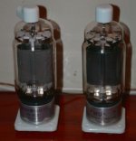
On the other hand, I also thought of these 814s as an output stage.
Do you think they would make a good guitar amp?
The 813 pair would be my final choice,
but that would require an entirely different power transformer,
filaments, and even topology.
I had thought of design-centering around the 6BG6As,
instead of the 6L6GCs, although I wanted to make them both options.
On the other hand, I also thought of these 814s as an output stage.
Do you think they would make a good guitar amp?
The 813 pair would be my final choice,
but that would require an entirely different power transformer,
filaments, and even topology.
Attachments
Last edited:
The 813 pair would be my final choice
There have been a few links to this mentioned in this forum (why use just two 813's):
Champ 1000 Watt Tube Amp
One of them is from this thread which outlines a few big amps. Some are guitar amps:
http://www.diyaudio.com/forums/tube...r-tube-amps.html?highlight=champ+1000W+guitar
I don't have any 814's. I do have some 813's and 828's but I now think that the high voltages and impedances needed don't make for easy designs. I also have a bunch of 833A's and even made a little practice amp with one just to see how it sounds. None of this is really practical and all of the tubes and associated transformers will get sold.
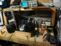
The 200 watt practice amp:
The 833A SE Amp Prototype
Attachments
Wow I love this: It looks like the bench could kill a rhinoceros!
This quote is Tube Lore Gold:
involuntarily by just hearing the legendary story;
around campfires made with burning boxes of carbon resistors.
When something is both Tube-Lore Gold and also
Back to the Future Comedy Gold,
it becomes pure Thoriated Platinum.
Please don't electrocute the cat: This is too valuable to lose.
Where in the picture is the Flux Capacitor?
One more item:
when I hear those two phrases joined in one sentence:
"200 watt" ................"practice amp"
Just the thing that moms everywhere dread,
covering the ears of little boys who have not yet conceived of the idea...
This quote is Tube Lore Gold:
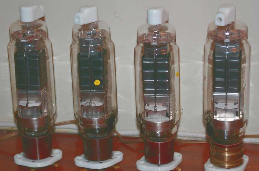
This is the kind of mad experiment that all tubaholics must live vicariously through,Observations so far:
The 10 amp filament puts out a serious AC magnetic field that gets into everything. Hum is evident in the speakers and on the analyzer BEFORE you turn on the power supply. As soon as you plug in the filament transformer the hum appears. Moving the transformers or the tube around has no effect. The hum balance pot has no effect on this hum. DC filaments WILL be required.
The low frequency response is outrageous. Roll off starts around 25 Hz and 3 db is 11 Hz.
involuntarily by just hearing the legendary story;
around campfires made with burning boxes of carbon resistors.
When something is both Tube-Lore Gold and also
Back to the Future Comedy Gold,
it becomes pure Thoriated Platinum.
Please don't electrocute the cat: This is too valuable to lose.
Where in the picture is the Flux Capacitor?
One more item:
I can't tell you how much high voltage goes through my enthusiasm circuit,The 200 watt practice amp:
when I hear those two phrases joined in one sentence:
"200 watt" ................"practice amp"
Just the thing that moms everywhere dread,
covering the ears of little boys who have not yet conceived of the idea...
Last edited:
Yes, I saw this monster amp already.why use just two 813's
But it looks like I'd have to roll my own 80 lb transformers,
or else have industrial power trannys brought in by forklift.
I have already committed to using a light and inexpensive
switching power supply for the 10 volt 10 amp heaters with
just two tubes....
But the High Voltage problem I was going to solve multiple ways,
starting with using lower voltages than the max possible...
and running class A.
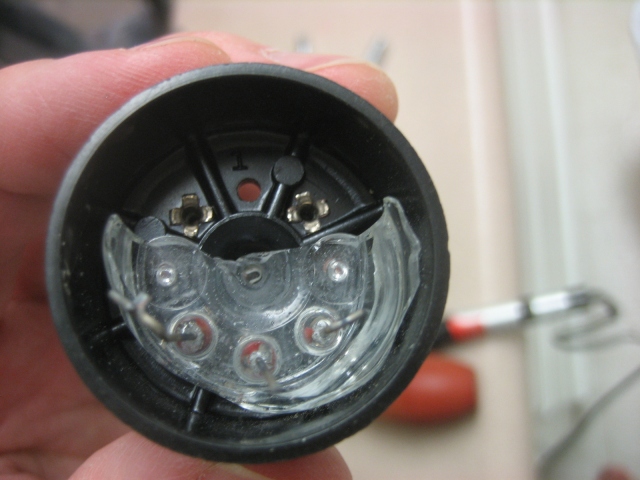
I'm going to use both types of power-tube clip on these amps,
because they are hanging upside down.
First these ones, which grip the base:

Then these ones, to hold those babies in regardless of roady mishaps.

I know: You're saying, "Why both?"
Because I don't trust either method.
Of course this brings to mind the train scene in Once Upon a Time in the West.
Frank: "How can you trust a man who wears both a belt and suspenders? The man can't even trust his own pants. "
My only misgivings are the potential for shorts/arcing from metal retainer to topcap clip/plate (with 6BG6As).
I may have to use an additional silicon (for heat resistance) insulating ring with a ridge.
because they are hanging upside down.
First these ones, which grip the base:
Then these ones, to hold those babies in regardless of roady mishaps.
I know: You're saying, "Why both?"
Because I don't trust either method.
Of course this brings to mind the train scene in Once Upon a Time in the West.
Frank: "How can you trust a man who wears both a belt and suspenders? The man can't even trust his own pants. "
My only misgivings are the potential for shorts/arcing from metal retainer to topcap clip/plate (with 6BG6As).
I may have to use an additional silicon (for heat resistance) insulating ring with a ridge.
Last edited:
- Status
- This old topic is closed. If you want to reopen this topic, contact a moderator using the "Report Post" button.
- Home
- Live Sound
- Instruments and Amps
- 6L6GC / 6BG6 x4 Ultralinear Guitar Amp