No reason why you can not run a separate transformer for the heaters, I do it all the time. I adjust my variac up or down to get the voltage I want.
A VVR works wonders also.
No reason why not.
But readers should keep in mind that most guitar amps (and most amps),
have the heater winding on the same transformer as the HV winding.
You simply can't hook up a typical guitar amp to a variac safely.
If you have the luxury of building a modular design on your testbench,
or you are willing to modify an amp to provide a separate heater-transformer,
and a special insert to put a variac between the mains and the HV transformer without affecting the heater voltage,
that is certainly awesome, but quite out of reach for most amp-owners.
Even amp builders are not likely to provide separate powerline inputs so that people could safely vary HV supplies without affecting the heater supply.
That would require two separate powerlines and/or a special insertion system on the back of the amp for your variac.
..meant to add that last phrase.No reason why not.
But readers should keep in mind that most guitar amps (and most amps),
have the heater winding on the same transformer as the HV winding.
You simply can't hook up a typical guitar amp to a Variac safely and then turn down the voltage.
.
In the diagram above, we have the usual 6L6 curve family, where we are supposed to draw a load line.
Trouble is, the output stage doesn't have a resistive load, so the normal facts don't apply.
With an ordinary resistor load, the tube acts like a variable voltage divider,
and naturally, we can draw a load line by taking the extreme points:
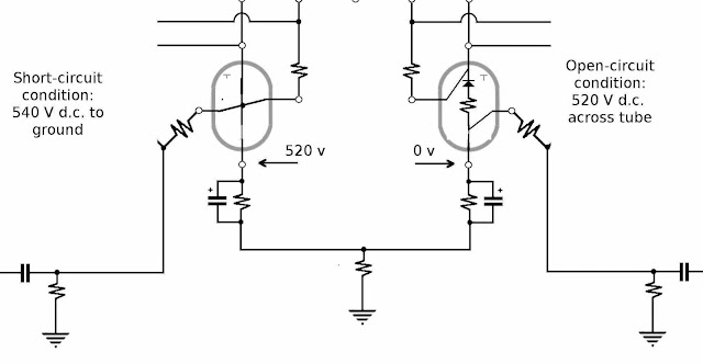
(1) Tube off - complete current shut down (resistance = infinity): now the full power-supply voltage appears across the tube (sort of). Since there is no current, there is no voltage drop across the plate resistor, and the full B+ is at the plate (to ground). This is where the tube goes into "Class AB/B" and turns off for part of a cycle with a big signal swing. The danger at this point is arcing inside the tube, or surface traces/flashes across the pins/socket, if the voltage is too high. or the sockets are dirty or the air is too humid.
(2) Tube full on - minimal resistance, maximum current (resistance = remaining load): now there is no significant voltage across the tube, and most of the voltage appears across the resistor load. For a tube with a plate-load, the plate reads zero volts relative to ground, and the voltage drop across the resistor is the full voltage (minus any voltage drop across a cathode resistor in series with both the tube and load). The danger here is overloading thin wires (usually the grids) with too much current, red heat, meltdown, and tube death. Another potential danger is tube wear: cathode-stripping from over-current and over-heating. Nonetheless even when fully conducting, there isn't really a full short-circuit, since the resistive load (and any cathode resistor) is still in series with the B+
These two extremes serve to provide end-points for a load line, drawn as above (from highest voltage across tube /no current over to lowest voltage / max current). The tube voltage and current is assumed to follow Ohm's Law (a straight line on the chart between the points).
Normally, we would pick an appropriate HV (B+) which fixes one end of the load line,
and then pick an appropriate load impedance (Z-primary) that nails the other end down.
However, we already have a power transformer (fixing choices of B+),
and an output transformer (fixing maximum current and the angle of the load line).
The only question remaining, is where the tube will 'idle' (i..e, its quiescent current), that is, what resistance will it present, and what current will be flowing through it when there is no other signal on the control grid (g1) other than the DC Bias voltage. This idle point is what WE get to set, by picking an appropriate Bias voltage.
We do it by picking an appropriate mid-point on our line, and a modest idle current, then reading (or estimating) what the BIAS voltage will have to be to hold the tube there.
For Class A (full operation) usually we want a good (equal) swing in both directions that stays in safe range and keeps the heat dissipation below the maximum ratings.
The same basic procedure is used for pentode, Ultralinear or Triode modes.
But with pentodes, we want the load angle to avoid dipping into the 'elbow'
and with triode modes we want to follow more conservative ratings and watch screen current, but its the same idea.
In our amplifier, we can't actually pick our own load line, because we already have the transformer, which is fixed at a supposedly 5k ohm impedance.
We can still pick an 'idle' point however, just as with a car we can't change the horsepower or torque, but we can adjust the 'idle RPM' to save gas but keep from stalling.
Trouble is, the output stage doesn't have a resistive load, so the normal facts don't apply.
With an ordinary resistor load, the tube acts like a variable voltage divider,
and naturally, we can draw a load line by taking the extreme points:
(1) Tube off - complete current shut down (resistance = infinity): now the full power-supply voltage appears across the tube (sort of). Since there is no current, there is no voltage drop across the plate resistor, and the full B+ is at the plate (to ground). This is where the tube goes into "Class AB/B" and turns off for part of a cycle with a big signal swing. The danger at this point is arcing inside the tube, or surface traces/flashes across the pins/socket, if the voltage is too high. or the sockets are dirty or the air is too humid.
(2) Tube full on - minimal resistance, maximum current (resistance = remaining load): now there is no significant voltage across the tube, and most of the voltage appears across the resistor load. For a tube with a plate-load, the plate reads zero volts relative to ground, and the voltage drop across the resistor is the full voltage (minus any voltage drop across a cathode resistor in series with both the tube and load). The danger here is overloading thin wires (usually the grids) with too much current, red heat, meltdown, and tube death. Another potential danger is tube wear: cathode-stripping from over-current and over-heating. Nonetheless even when fully conducting, there isn't really a full short-circuit, since the resistive load (and any cathode resistor) is still in series with the B+
These two extremes serve to provide end-points for a load line, drawn as above (from highest voltage across tube /no current over to lowest voltage / max current). The tube voltage and current is assumed to follow Ohm's Law (a straight line on the chart between the points).
Normally, we would pick an appropriate HV (B+) which fixes one end of the load line,
and then pick an appropriate load impedance (Z-primary) that nails the other end down.
However, we already have a power transformer (fixing choices of B+),
and an output transformer (fixing maximum current and the angle of the load line).
The only question remaining, is where the tube will 'idle' (i..e, its quiescent current), that is, what resistance will it present, and what current will be flowing through it when there is no other signal on the control grid (g1) other than the DC Bias voltage. This idle point is what WE get to set, by picking an appropriate Bias voltage.
We do it by picking an appropriate mid-point on our line, and a modest idle current, then reading (or estimating) what the BIAS voltage will have to be to hold the tube there.
For Class A (full operation) usually we want a good (equal) swing in both directions that stays in safe range and keeps the heat dissipation below the maximum ratings.
The same basic procedure is used for pentode, Ultralinear or Triode modes.
But with pentodes, we want the load angle to avoid dipping into the 'elbow'
and with triode modes we want to follow more conservative ratings and watch screen current, but its the same idea.
In our amplifier, we can't actually pick our own load line, because we already have the transformer, which is fixed at a supposedly 5k ohm impedance.
We can still pick an 'idle' point however, just as with a car we can't change the horsepower or torque, but we can adjust the 'idle RPM' to save gas but keep from stalling.
Last edited:
No reason why not.
But readers should keep in mind that most guitar amps (and most amps),
have the heater winding on the same transformer as the HV winding.
You simply can't hook up a typical guitar amp to a variac safely.
If you have the luxury of building a modular design on your testbench,
or you are willing to modify an amp to provide a separate heater-transformer,
and a special insert to put a variac between the mains and the HV transformer without affecting the heater voltage,
that is certainly awesome, but quite out of reach for most amp-owners.
Even amp builders are not likely to provide separate powerline inputs so that people could safely vary HV supplies without affecting the heater supply.
That would require two separate powerlines and/or a special insertion system on the back of the amp for your variac.
Yeah but you are building a one-of ultimate guitar amp unlike what others have done before you and what is out of the reach of the average aowner really does not apply, does it?
Yeah but you are building a one-of ultimate guitar amp unlike what others have done before you and what is out of the reach of the average aowner really does not apply, does it?
Well, the situation certainly is a bit abnormal.
But similar barriers are in place.
My philosophy for this project was/is:
(1) Use what I have on hand, as much as possible.
(2) Build the best amp I can performance wise, constrained by very limited budget.
(3) Learn and share the experience-curve so others can benefit.
In this case, although I could presumably build in HV adjustments (and may have a few switch/options yet), a Variac is not practical, since I will probably want the amp to be portable, and foolproof (more design parameters!).
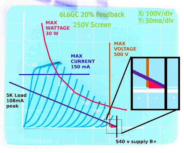
Looking at the 'load line' here again,
you'll notice I have highlighted the bottom right corner.
Here is where, if the grid was driven far enough, we would cross
the 500 volt barrier, and find the full voltage bearing down on the tube.
Now a 5881 is only rated at 400-450 volts,
and even our tube of choice, the big 6L6GC, is rated at 500 max.
We dropped about 50 volts across the 1.3k cathode resistor
we plan to use for self-bias. This significantly lowers the voltage across the tube,
as long as it is conducting current (Class A/AB).
This seems to offer enough protection for a 6L6GC (540 - 50 = 490 volts avail.) ...
...and here comes the catch: as long as it is conducting!.
However, as soon as the tubes start shutting down, the voltages again climb too high for safety.
We need to look at why the 6L6GC was rated at 500 volts in the first place:
People were getting shocked trying to change tubes with a top plate-cap carrying 500-800 volts,
and makers (tube makers too) wanted to reduce risk and liability,
so tubes without plate-caps and designed to run on lower voltages were promoted.
Moving the plate-cap to the base however, made higher voltages unreliable,
because of arcing and tracing at the socket
(and arcing inside the tube with smaller gaps between elements inside the tubes!).
We can overcome this problem by (you guessed it!)
reverting back to top-cap plate connections, namely using a
6BG6A instead of a 6L6 as our tube of choice.

As it turns out, the 6BG6A is a Higher Voltage version of a 6L6,
like the 807 and 1625 tubes (only more modern).
And its a hell of a lot cheaper than good 6L6GC tubes too!
I happened to pick up a box of them for a few dollars apiece.
With proper HV wire and caps, and a safety-screen to keep idiot-fingers
out of harm's way, this seems like the ultimate solution.
Even if we could squeak a 6L6GC in our circuit using self-bias,
at lower risk, the 5881 would be right out, at a max of 400 volts.
We will test the amp with the 6BG6s, then look into making some options
for retrofitting 6L6GCs or 5881s in a pinch.
The 807 and 1625 would do equally well electrically,
however, we'd also have to invest in special 5-pin or 7-pin sockets (expensive),
which are also unsuitable for tube-substitution or swap-outs.
An externally hosted image should be here but it was not working when we last tested it.
Last edited:
I've been told repeatedly that this was one of Van Halen's (off the cuff interview) pranks.
That is, he really didn't use a variac,
unless perhaps experimentally in studio once, and its not a part of his 'sound'.
Those running out to try this ought to take serious heed of the obvious warnings, such as:
(1) A variac on most amps would also drop the heater voltage,
and this directly contributes to tube death.
So much so that RCA did a long comprehensive study
and warned designers not to vary the heater voltage
from recommended values more than 4%:
LOWER VOLTAGES especially KILL TUBES QUICKLY.

With 85% of the rated voltage on a tube, it goes from a 5,000-hour+ tube to a 3-hour tube!.
Letting your tech experiment with a variac on your amp for a couple of hours will cost you a whole set of tubes within weeks of installation!
Don't let the heater voltage on your tube drop below 96% for any extended length of time:
12.6 v heater (signaltubes): greater than 12.1 volts or else! (Never use 12 volt regulators (7812) without resistor adjusts)
6.3 v heater (powertubes): greater than 6.05 volts or else! (Never use 6 volt regulators (7806) without resistor adjusts)
I bet Eddie has enough coin for as many valves as he wants!
My philosophy has always been that the best guitar amps distort from the output stage progressively thru to the input: like a "Train Wreck", which doesn't follow any of the rules. Leo Fender defiantly wasn't an EE but a nice old "Bassman" certainly sounds good to me! I bet Leo used whatever grid stoppers he happened to be able to buy cheap! Its Guitar, not Hi Fi. Its supposed to distort
...so anyway, to recap (no pun intended),
We're going for 6BG6As instead of 6L6GCs.
The basic curves stay the same, but the maximum voltage ratings are increased, allowing "class B" operation,
or excursion into current cutoff as the driving signal crosses over between output tubes (or pairs!).
But we still have some problems with the 'load line':

Although we treat the reactive transformer and speaker-load as if it were a resistive load for purposes of drawing the load line,
the premise is basically false, and the real tube behavior will be nowhere near what the load-line suggests:
(1) Suppose we pick an idle-point of 50 mA, which would require a bias of 50 volts, and according to the load-line would leave 300 volts on the plate (dropping a vertical down to the x-axis).
(2) Of course we all should know that the transformer is not a resistor, but only a 'nominal A.C. impedance' of 5k. Its actual (measured) resistance is only 50 ohms per side (on mine anyway).
This means that with 50 mA coursing through it on idle with no AC signal, its only dropping about 2.5 volts, leaving 538.5 volts from ground on the plate! Of course, our self-bias cathode resistor takes up about 67 volts (at 1350 ohms), leaving 471 volts from cathode to plate. Thats safe (while idling) for a 6L6, but not a 5881.
(3) All this suggests that any AC signal at the plate is really riding on a 471 volt D.C. offset voltage (relative to the cathode), and we should really shove our load line over to the right about 171 volts! (or move the scale 171 volts to the left).
(4) A 50v +-, or 100v Peak to peak input voltage, on one tube grid would swing the voltage at the plate about 360 volts, or from 290 to 650 volts + relative to the cathode. Only the 6BG6A will be able to handle that kind of spread.
We're going for 6BG6As instead of 6L6GCs.
The basic curves stay the same, but the maximum voltage ratings are increased, allowing "class B" operation,
or excursion into current cutoff as the driving signal crosses over between output tubes (or pairs!).
But we still have some problems with the 'load line':
Although we treat the reactive transformer and speaker-load as if it were a resistive load for purposes of drawing the load line,
the premise is basically false, and the real tube behavior will be nowhere near what the load-line suggests:
(1) Suppose we pick an idle-point of 50 mA, which would require a bias of 50 volts, and according to the load-line would leave 300 volts on the plate (dropping a vertical down to the x-axis).
(2) Of course we all should know that the transformer is not a resistor, but only a 'nominal A.C. impedance' of 5k. Its actual (measured) resistance is only 50 ohms per side (on mine anyway).
This means that with 50 mA coursing through it on idle with no AC signal, its only dropping about 2.5 volts, leaving 538.5 volts from ground on the plate! Of course, our self-bias cathode resistor takes up about 67 volts (at 1350 ohms), leaving 471 volts from cathode to plate. Thats safe (while idling) for a 6L6, but not a 5881.
(3) All this suggests that any AC signal at the plate is really riding on a 471 volt D.C. offset voltage (relative to the cathode), and we should really shove our load line over to the right about 171 volts! (or move the scale 171 volts to the left).
(4) A 50v +-, or 100v Peak to peak input voltage, on one tube grid would swing the voltage at the plate about 360 volts, or from 290 to 650 volts + relative to the cathode. Only the 6BG6A will be able to handle that kind of spread.
When drawing load lines for push pull amps you use 1/4 the plate to plate impedance. In this case 1.25K. This is what each tube sees on it's side of the output transformer to B+. Also, plate voltage can reach twice the B+ voltage when the tube on the other side is conducting hard.
To take a step away from the theoretical, I am posting X-Y plots of a 5881 in an actual guitar amp driven by a guitar. Sorry it's not an ultralinear output stage, but I don't expect one to be much different. The amp is a 5F6A re-issue from the 90's with GZ34 rectifier. Current is sampled by a 1 ohm resistor in series with the cathode. Plate voltage is measured by a 1000x probe connected to the scope's horizontal. (Don't try this at home unless you have the proper equipment.) In the first attachment, left most pic, I have sketched the plate curves and the 30W plate dissipation line. Note the screen voltage is such that plate current can reach over 400mA. The second pic shows the bias point. The 3rd pic is the load line with a 2 ohm resistive load. (The 5F6A drives four 10 inch 8 ohm speakers in parallel.) The second attachment shows what happends when playing guitar through the speakers. Note instantaneous plate dissipation can be well over 30 watts, plate voltage easily reaches 800V and can go negative several hundred volts.
This is the kind of stress that a guitar amp puts on it's output tubes.
Yes, I'm aware that a 5881 is only rated at 23 watt plate dissipation. These tubes are marked "5881 MADE IN USSR" re-branded "Ruby 6L6GCRI/5881 Made in Russia".
Attachments
Last edited:
Thank God that Fender makes crappy amps!
Turning to the physical construction problem,
I have solved this by the simple expedient of buying a piece of crap.
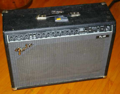
The Fender Pro 185 is admittedly a loud amp.
Unfortunately, its 'sound' is crudely synthesized by transistor/op-amp technology.
Typically, these amps (like all amps) develop problems like crunchy, noisey volume/tone pots, and crackly cutting-out symptoms, which are notoriously difficult to hunt down and/or permanently fix.
So, such amps have the double-strike that they are both NOT TUBE AMPS, and they have as many or more problems as tube amps.
As a result, their resale value is similar to that of an old foreign car, which offers expensive repair bills and little else.
Yet, for the savvy amp-builder, these boxes have one redeeming feature:
They are about the same in construction as a good Fender Twin Reverb (Tube version).
Obviously, the speakers, having to handle the same power, are the same, and so is the cabinet. To buy these parts individually would be cost-prohibitive, and to build a cabinet, while a worthwhile project on its own for a woodworker, is as expensive as just cannibalizing one.
So I picked up such a crappy amp used, for under $200.
Speaker and Cabinet problem solved:
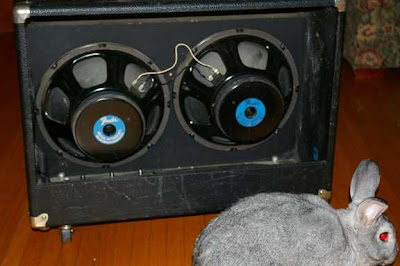
These speakers are just about the best I could get,
because they are even better than typical Marshalls.
They are designed for abuse, and don't require mounting
in a sealed cabinet, but can handle pretty severe excursions,
and a lot of wattage.
The equivalent 140 watt Fender cabinet without amp would run about $500 new!
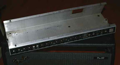
But the additional bonus is of course a virtually clean chassis,
with all the mounting parts and re-useable hardware,
e.g., A.C. cable, On switch, silkscreened frontplate etc. etc.
This is another good reason not to sneer at crappy old amps,
that would cost an arm and a leg to fix:
They are natural part-sources.
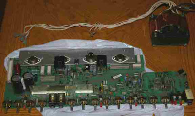
In fact,
here is the 140 watt transistor amp , complete with power tranny,
which I will sell as is for parts to repair another amp,
no reasonable offer refused! (Buyer pays shipping).
I may have to cut back or rebend/fold the chassis,
but that is a small price to pay for securing a solid,
practical platform for my amp project.
This was a case of money well spent on this project.
Turning to the physical construction problem,
I have solved this by the simple expedient of buying a piece of crap.
The Fender Pro 185 is admittedly a loud amp.
Unfortunately, its 'sound' is crudely synthesized by transistor/op-amp technology.
Typically, these amps (like all amps) develop problems like crunchy, noisey volume/tone pots, and crackly cutting-out symptoms, which are notoriously difficult to hunt down and/or permanently fix.
So, such amps have the double-strike that they are both NOT TUBE AMPS, and they have as many or more problems as tube amps.
As a result, their resale value is similar to that of an old foreign car, which offers expensive repair bills and little else.
Yet, for the savvy amp-builder, these boxes have one redeeming feature:
They are about the same in construction as a good Fender Twin Reverb (Tube version).
Obviously, the speakers, having to handle the same power, are the same, and so is the cabinet. To buy these parts individually would be cost-prohibitive, and to build a cabinet, while a worthwhile project on its own for a woodworker, is as expensive as just cannibalizing one.
So I picked up such a crappy amp used, for under $200.
Speaker and Cabinet problem solved:
These speakers are just about the best I could get,
because they are even better than typical Marshalls.
They are designed for abuse, and don't require mounting
in a sealed cabinet, but can handle pretty severe excursions,
and a lot of wattage.
The equivalent 140 watt Fender cabinet without amp would run about $500 new!
But the additional bonus is of course a virtually clean chassis,
with all the mounting parts and re-useable hardware,
e.g., A.C. cable, On switch, silkscreened frontplate etc. etc.
This is another good reason not to sneer at crappy old amps,
that would cost an arm and a leg to fix:
They are natural part-sources.
In fact,
here is the 140 watt transistor amp , complete with power tranny,
which I will sell as is for parts to repair another amp,
no reasonable offer refused! (Buyer pays shipping).
I may have to cut back or rebend/fold the chassis,
but that is a small price to pay for securing a solid,
practical platform for my amp project.
This was a case of money well spent on this project.
When drawing load lines for push pull amps you use 1/4 the plate to plate impedance. In this case 1.25K. This is what each tube sees on it's side of the output transformer to B+. Also, plate voltage can reach twice the B+ voltage when the tube on the other side is conducting hard.
To take a step away from the theoretical, I am posting X-Y plots of a 5881 in an actual guitar amp driven by a guitar. Sorry it's not an ultralinear output stage, but I don't expect one to be much different. The amp is a 5F6A re-issue from the 90's with GZ34 rectifier. Current is sampled by a 1 ohm resistor in series with the cathode. Plate voltage is measured by a 1000x probe connected to the scope's horizontal. (Don't try this at home unless you have the proper equipment.) In the first attachment, left most pic, I have sketched the plate curves and the 30W plate dissipation line. Note the screen voltage is such that plate current can reach over 400mA. The second pic shows the bias point. The 3rd pic is the load line with a 2 ohm resistive load. (The 5F6A drives four 10 inch 8 ohm speakers in parallel.) The second attachment shows what happends when playing guitar through the speakers. Note instantaneous plate dissipation can be well over 30 watts, plate voltage easily reaches 800V and can go negative several hundred volts.
This is the kind of stress that a guitar amp puts on it's output tubes.
Yes, I'm aware that a 5881 is only rated at 23 watt plate dissipation. These tubes are marked "5881 MADE IN USSR" re-branded "Ruby 6L6GCRI/5881 Made in Russia".
This is great stuff!
I love the wild and woolly voltage/current excursions in your photos. Looks like a reflection of the reactance/phase effects of the speaker-load, and the lack of a stabilizing high resistance in series with the tube.
When drawing load lines for push pull amps you use 1/4 the plate to plate impedance. In this case 1.25K. This is what each tube sees on it's side of the output transformer to B+. Also, plate voltage can reach twice the B+ voltage when the tube on the other side is conducting hard.
.
The point about the actual impedance seen by one tube on one side is a great note.
Also, the fact that the plate-voltage can swing as high as 2 x B+
is a real warning that shouldn't be ignored.
I was actually being conservative in my concerns about voltage and internal tube-arcing.
Although the published ratings for NOS tubes are usually design-center values (with swings outside the max expected),
two things cause additional caution:
(1) modern tubes don't act like NOS tubes.
(2) design-center maxs don't have in view guitar-amp overloading, high extended current periods, and full sine-wave RMS signals on input grids.
We see a trend in many newer amp designs of lower base plate voltages (HV B+ design choices), and a return to tube-rectification and even PS choke mods.
How much are they derating the new amp voltages as compared to old? Do they bump up the current to get the same wattage amp or not?
Thank God that Fender makes crappy amps!
Maybe their newer ones, but that's already been debated ad nauseum.
")
This is another good reason not to sneer at crappy old amps,
that would cost an arm and a leg to fix:
They are natural part-sources.
This was a case of money well spent on this project.
This is an great point and a great tip! I'm going to start looking for a 1x12 combo to use for my next project.
How much are they derating the new amp voltages as compared to old? Do they bump up the current to get the same wattage amp or not?
I think there is less wattage too, but nobody will notice,
because the difference between 70 watts and 100 watts is less than 1 db!
So I picked up such a crappy amp used, for under $200. Speaker and Cabinet problem solved
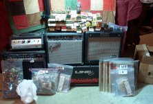
I hit the local (and some not so local) hamfests to sell my junk, and shop for rare treasures. I look for dead guitar amps for cabinet reuse. The picture below shows the haul I brought back from the Orlando hamfest in February. I was looking for tubes when I got a phone call about a guy selling a Marshall 4 X 12 cabinet loaded with Celestions for $100. I ran to the location to find a friend buying it. The seller had several dead guitar amps that had been tweaked to death by an "expert". Some were missing parts. I purchased them ALL for $25 total.
I traded away the reverb unit at another hamfest. Got a Stratocaster in that deal. I have often found and sold audio and guitar equipment at hamfests. The interest is low, so are the prices. Rare pieces have high prices and don't sell. There was a Gibson SG at Orlando with a $600 price. That was a good price for that guitar, but people don't go to hamfests to spend $600 on a guitar.
I dragged them home and autopsied them all.
There was a Fender G-DEC (Guitar Digital Entertainment Center). I was curious enough about it to fix it. It is like the guitar equivalent of a Karaoke machine. It is unique enough as a TOY to keep me interested for now. I will sell it when it loses my interest.
The other three have been judged to be certified cabinet donors. The speaker in the Crate might be a keeper. The Fender Frontman speaker didn't like being fed 125 watts of tube amp scream and it has been permanently silenced!
I haven't said anything about the amp in this thread since the OP obviously has strong opinions on the subject, but here is my $.02. I have been making tube guitar amps since the 60's. Back then I used parts from old TV sets to make what I could. I can now build whatever I want, and will often breadboard something just to see what it sounds like.
It has been said that UL doesn't work for guitar amps. I tend not to listen to what others say, so I have tried it. I tried SE UL, and P-P UL. UL just doesn't sound right when the output stages are pushed into clipping. I have tried it a few times and never got anything that I liked, but your tastes may vary.
About 2 years ago I decided to build a "HiFi guitar amp". I used one of my HiFi amp boards (an SSE wired for P-P) and designed a preamp that had enough gain for a full metal racket if desired, but could be clean enough that the whole amp could do 50 watts at 2% distortion. I used two Hawthorne Silver Iris HiFi drivers because I had them and they can eat 100 watts each if needed. The amp sounded good and would be great for a keyboard, or acoustic guitar, maybe even an ES335 playing rythym. I however became bored with it after a few months and took it apart.
I am now building a semi holow body guitar, so I may revisit the HiFi guitar amp again, who knows.
Attachments
Great haul!I hit the local (and some not so local) hamfests to sell my junk, and shop for rare treasures. I look for dead guitar amps for cabinet reuse. The picture below shows the haul I brought back from the Orlando hamfest in February.
Nice score, even if you didn't get the 4x12.
At least its in the family so to speak.
Sounds just about right.I traded away the reverb unit at another hamfest. Got a Stratocaster in that deal. I have often found and sold audio and guitar equipment at hamfests. The interest is low, so are the prices. Rare pieces have high prices and don't sell. There was a Gibson SG at Orlando with a $600 price. That was a good price for that guitar, but people don't go to hamfests to spend $600 on a guitar.
I find that too. If I go to a non-musical pawn shop,
sometimes they underprice.
"I dragged them home and autopsied them all. "
I love this quote!
You make it sound as fun as it must have been.
The Crate ought to be good.The other three have been judged to be certified cabinet donors. The speaker in the Crate might be a keeper. The Fender Frontman speaker didn't like being fed 125 watts of tube amp scream and it has been permanently silenced!
I'm not surprised the Fender speaker died.
A brand name ain't gonna make up for lack of an adequate wattage rating.
I haven't said anything about the amp in this thread since the OP obviously has strong opinions on the subject, but here is my $.02. I have been making tube guitar amps since the 60's. Back then I used parts from old TV sets to make what I could. I can now build whatever I want, and will often breadboard something just to see what it sounds like.
It has been said that UL doesn't work for guitar amps. I tend not to listen to what others say, so I have tried it. I tried SE UL, and P-P UL. UL just doesn't sound right when the output stages are pushed into clipping. I have tried it a few times and never got anything that I liked, but your tastes may vary.
Yeah I was actually expecting a lot more flack for even mentioning UL modes.
I think you are right that untweaked UL ain't gonna be anything special guitar-amp wise.
But I had in mind this:
(1) UL gets you closer to triode than pentode mode, without losing too much power output.
(2) The type of distortion some crave coming from the the power-section seems to be based on a handful of independent factors:
a) OT saturation and impedance
b) the effects of screen-current in fixed-bias configurations, and the choice of resistors.
c) tube-type and frequency response under overdrive.
d) blocking distortion from the driver section just previous.
In my mind, these various desirable/undesirable effects are either independent of UL mode topology, or else can be brought into it or eliminated by design.
(3) UL simplifies PS design.
So I'm not ready to write off UL mode for guitar amps.
About 2 years ago I decided to build a "HiFi guitar amp". I used one of my HiFi amp boards (an SSE wired for P-P) and designed a preamp that had enough gain for a full metal racket if desired, but could be clean enough that the whole amp could do 50 watts at 2% distortion. I used two Hawthorne Silver Iris HiFi drivers because I had them and they can eat 100 watts each if needed. The amp sounded good and would be great for a keyboard, or acoustic guitar, maybe even an ES335 playing rythym. I however became bored with it after a few months and took it apart.
I am now building a semi holow body guitar, so I may revisit the HiFi guitar amp again, who knows.
I hear you on this.
There is no 'magic bullet' design.
And even favorites come and go with mood and developments.
A change is as good as a rest.
Any amps in particular?I think there is less wattage too, but nobody will notice,
because the difference between 70 watts and 100 watts is less than 1 db!
(1) UL gets you closer to triode than pentode mode, without losing too much power output.
Most think triode mode is too bland for guitar, that is unless you like clean.
(2) The type of distortion some crave coming from the the power-section seems to be based on a handful of independent factors:
a) OT saturation and impedance
One of the better upgrades done by guitar players is to beef up the OT if it is too wimpy. Never heard anyone say they would rather go back to the stoctk transformer once they upgraded.
d) blocking distortion from the driver section just previous.
Same seems to go with blocking distortion. It does not seem to be desirable.
- Status
- This old topic is closed. If you want to reopen this topic, contact a moderator using the "Report Post" button.
- Home
- Live Sound
- Instruments and Amps
- 6L6GC / 6BG6 x4 Ultralinear Guitar Amp