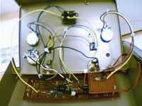
Here is a pic of the softclip board installed in the chassis, just need to finish wiring into the switch and NFB. Have in mind to mate it to the IC socket (main board) on the right, so I can remove the softclip board easily and add or change components in future. Tie wrapped some of the wires to clean it up a bit. That's it for this week..
Attachments
The softclip board is wired in to the switch and NFB circuit. Double checked the switching function to make sure it's in there correctly..starting to deal with a few wires now (and still looking at putting in the tone control). Looks like it is good to go..will fire it up tonight with fingers crossed and see how it sounds.
Tested out the softclip circuit last night, and it sounds good. It covers a more subtle range of distortion than the post op-amp clip circuits. With the bias in mid position it is a minimal distortion and going to either full CCW or CW brings it up to a more ''edgy'' distortion, almost to the post op-amp clip level with LED..the tone being pretty similar. Makes sense that the bias wiper position going to full CCW or CW would give a more asymmetric sound like the LED setting. And I like the fact that you can adjust anywhere in between, which was not exactly the case with the way the post op-amp LED clip works, although you get a similar result playing with the gain.
With the bias pot either going from Mid position to CCW or from mid position to CW, the ranges of distortion level /tone are pretty much the same. Because of that, I am going to try a cap across the bias wiper to one side of the bias pot. May give some tonal emphasis to the soft clip circuit depending on wiper position , but I am not certain of that yet.
With the bias pot either going from Mid position to CCW or from mid position to CW, the ranges of distortion level /tone are pretty much the same. Because of that, I am going to try a cap across the bias wiper to one side of the bias pot. May give some tonal emphasis to the soft clip circuit depending on wiper position , but I am not certain of that yet.
Further work/improvements to be done:
1-Install a tone circuit
2-Try different LEDs, I am trying to get better data sheet info on various types (If vs Vf curves)
3- Noticed at high gain settings I hear a tiny bit of ringing, not full out squeal though. Will install that 10 pF cap at the op-amp NFB loop, and see if it sounds better.
4-As somewhat expected on the soft/hard clip select switching I get a pop. The effect resulting from a momentary instant there is no NFB resistance (open) in the op amp circuit. So may be some modding to do on that.
If anyone has some suggestions regarding (mos)fet type transistors, I would be interested in trying them. FYI Right now I am using 2N3904 and 3905 pair.
Tone circuit
For the Tone circuit, I want to start with something relatively simple, seeing as I have 3 control pots already and 2 selector switches, one more control pot is about it for this build.
In the stock MXR schematic, at the signal output there is a 10KOhm resistor and 0.001 uF cap acting as a fixed low pass filter, and a really basic analysis gives a corner frequency around 15.9 kHz.
Now for my really basic adjustable tone circuit: with the tone pot turned all the way down (wiper to signal ground), my filter capacitor (call it Cx) will be in parallel with that 0.001 uF.
Again as a really (over) simplified calculation I picked 0.01 uF as the value to start with. That would give me 0.011 uF total so with the pot in that position I should get a corner frequency around 1.5 kHz.. That looks OK to me, for a ''treble cut''. I could set the cut frequency lower than that with a higher value Cx, but this is a starting point and I don't think more treble cut will be necessary.
Now looking at the tone pot wiper fully in the top position: that puts Cx in parallel across the 10 K ohm resistor. I know this is not exact, but if I look just at the Cx and the volume pot resistance (also 10 K) across that to ground , that combo is acting as a high pass at same corner frequency (around 1.5 kHz)...also looks OK to me for a start.
For the Tone pot resistance, I was figuring on 50K or 100 K, maybe 100K is better to not load down the signal output too much. Better run to the store today, don't have that pot value in my parts bin.
Toaster oven or my next tube amp chassis?
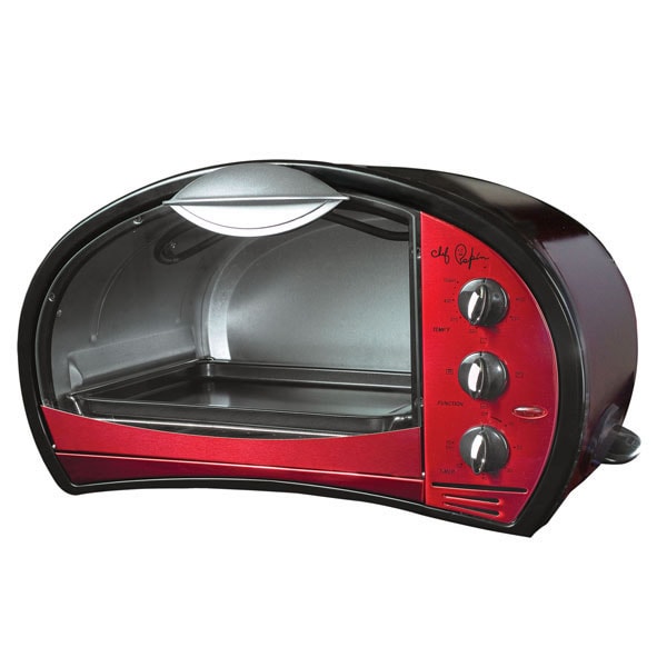
I was following another thread on DIY: Hundred Buck Amp Challenge, it is a great read and lots of interesting builds. I missed the deadline to get in on that, but I thought about a cheap way to get a neat chassis, heat resistant, control knobs and a window to see the tubes
I was following another thread on DIY: Hundred Buck Amp Challenge, it is a great read and lots of interesting builds. I missed the deadline to get in on that, but I thought about a cheap way to get a neat chassis, heat resistant, control knobs and a window to see the tubes
Tone circuit installed
Finished wiring in the preliminary Tone control. Got a 100K at the surplus store. Looked OK (was a $1.50) but we'll see, as the wiper action feels a bit rough..alright for the test.0.01uF mylar for Cx- Firing it up again tonight, and get back with results.
Finished wiring in the preliminary Tone control. Got a 100K at the surplus store. Looked OK (was a $1.50) but we'll see, as the wiper action feels a bit rough..alright for the test.0.01uF mylar for Cx- Firing it up again tonight, and get back with results.
I was following another thread on DIY: Hundred Buck Amp Challenge, it is a great read and lots of interesting builds. I missed the deadline to get in on that, but I thought about a cheap way to get a neat chassis, heat resistant, control knobs and a window to see the tubes
I think it would make an excellent chassis. It would look better as an amp than a toaster

Final test of the Tone circuit
I played through the pedal last night. The tone circuit is working correctly, and I am glad I added one. Because this pedal has a lot of options for gain and clipping type, it really helps to be able to ''tune-in'' and get a good workable range of sounds. The boost / rolloff frequency is about where I expected, and I may increase the value to get a bit lower corner frequency. IMO tone is a matter of subjective taste, so I am sure that many filter network arrangements could work, but for this pedal I figured the simpler the better.
I played through the pedal last night. The tone circuit is working correctly, and I am glad I added one. Because this pedal has a lot of options for gain and clipping type, it really helps to be able to ''tune-in'' and get a good workable range of sounds. The boost / rolloff frequency is about where I expected, and I may increase the value to get a bit lower corner frequency. IMO tone is a matter of subjective taste, so I am sure that many filter network arrangements could work, but for this pedal I figured the simpler the better.
Initial build 99% complete
The distortion pedal as pretty much built up to the modded schematic that I posted. I still have to solder in the 10 pF in the NFB loop, just to minimize any potential ringing at high gain setting. As this is a working prototype now, I want to finish off a few details so that is user-friendly at jams and gigs.
The softclip circuit really suits my taste and style of playing...and a guitarist friend of mine is already asking me to build up one for him.
I will post some decent photos of the finished pedal, once I get the last few details completed.
Overall I am glad I finally got this build to where it is, with all the mods in place, it was worth the time.")
The distortion pedal as pretty much built up to the modded schematic that I posted. I still have to solder in the 10 pF in the NFB loop, just to minimize any potential ringing at high gain setting. As this is a working prototype now, I want to finish off a few details so that is user-friendly at jams and gigs.
The softclip circuit really suits my taste and style of playing...and a guitarist friend of mine is already asking me to build up one for him.
I will post some decent photos of the finished pedal, once I get the last few details completed.
Overall I am glad I finally got this build to where it is, with all the mods in place, it was worth the time.
Instead of a 10 pF in the op amp NFB, I threw in a 50 pF..interesting change in tone/distortion character. The highs come through less distorted on the soft clip, and no ringing at all. I figure that I will try a 5pF too and see where it goes. That is the thing with a working prototype, it is never quite finished(!) Will eventually order up some mosfets to try them. Pictures of finished pedal will follow soon.
With the 5 pF installed the tendency for ringing at high gain settings is gone, but that value keeps the original tone.
Ordered up the mosfets, along with a couple of hammond 1590DD enclosures. Friend of mine borrowed the prototype pedal for a couple of weeks, really happy with the tone and now wants one in the big enclosure, with a few bells and whistles thrown in.
Also another thanks to Arick for picking up that octagonal hammond enclosure..I have another pedal build in mind for that.
overdrive to the next level
I did a lot of review and research about the various techniques to get a ''tube like'' sound. Some on-line commercial info is just that..commercial.
Even an overdrive/distortion pedal with a real single tube will sound just like that: a single tube that is overdriven.
I did some tests with the softdrive circuit and played around with the configuration. I got my Mosfets now and ready to do some more tests.
IMO the soft drive circuit gives a much more transparent and open sound. In some respects it is "tube like" ,or going in that direction. I am pretty critical about pedals, and this circuit already is beating out two commercial overdrive pedals off my board.
That leads me toward the next level and a comment,
What I think most players "want" in a pedal is not tube type distortion...but tube amp type distortion. That covers a lot of ground, and a lot of of amp types. But the ideal, at least for me, is that the effect pedal needs to give a depth of sound and dynamic response. It should not be a one dimensional effect. In the thread that was previously discussing this (referred at the opening page) some people were stating they preferred post op amp clipping, some preferred the clipping within the NFB. Symetrical or Asymetrical. That is all fine and good if that were all there was to do.
But there is much more to be done, and if people are interested..discuss.
I will leave it at that..any comments are welcome
wow, good stuff! i think my build was a little more extreme, i used a TL084 (input/output buffer and 2 gain stages) but i like this, instead of putting 2 resistors in series with the transistors i put a 2.2m log pot from bases of the transistors to th op amp output and the result seems similar to your bias controll.
Hi Razorrick, I think that is the direction to be going in, with a couple of gain stages and ''subtle'' adjustment of the overdrive. My impression was that the sound ends up with a lot more detail, because it is not clipping off too much of the signal's information. When I had the stock symmetrical Ge diodes at the op amp output (original circuit MXR Dist Plus) the distortion was ''decent'' but almost no dynamic touch response.
For your bias is the log pot 2.2M resistance wired across both bases , with the wiper connected to op amp output? That is an interesting way to do it.
I have also run the soft clip with a ''clean'' preamp/buffer pedal in front that I built up couple of years ago, and the range of sounds was indeed very good. With the ''clean'' preamp's gain control you can adjust the signal to hit the soft clip circuit a little stronger.
I am anxious to try the soft clip with the Mosfets and a couple of other ideas.
the first gain stage was mainly for tone shaping, seeing as i was trying to get a range of tones it had some extreme low cut and a little high cut (i think i went up to about 1k for the low cut and 9k with the high cut) with some hi/midcut after to level it out. the pot i put in wasnt so much a bias control, but it seemed to change to clipping point of the transistors with 2.2M (wiper connected to transistor bases, both bases are connected, pin 1 of pot connected to op amp output pin 3 left unconnected. it seems to set the level it clips at, with no resistance was a very hard clip, and 2.2M a much softer clip. i have not yet tried it with mosfets (havnt been able to get hold of the p type equivalent of a 2n7000) though i think the best op amp distortion ive heard so far is with a +/- 18v supply with 2 EB91 double diode valve in the FB loop driven by another opamp.
OK I am sure that config of the pot would work well too. No resistance at base of transistor is basically diode connected hard clip and then adding series base resistance to the signal will make the BJT turn on more gradually and requiring higher signal to drive through the base voltage.
I am sure the double EB91 would sound sweet..would love to hear it. Nice transfer curve.
Did you or would you build it?That would be another interesting topic!
Regards
Shanx
I am sure the double EB91 would sound sweet..would love to hear it. Nice transfer curve.
Did you or would you build it?That would be another interesting topic!
Regards
Shanx
Thats right, i guess its more of a "headroom" control. as for the EB91 set up i havnt built one yet, i havnt got one laying around, but il definately be trying it soon, i was thinking of buying a peavey valveking and swapping the sillicon clipping diodes with EB91's might make it a bit better, and valvekings are pretty cheap.
Mosfet clip
Been a while since I posted. I was looking into tying G and D together on the mosfets I have using them as 'diode' configuration, and this has been done in some commercial design stuff. There are some issues, because a mosfet example 2N7000 like others has an internal connected body diode. In some , but not all, commercial mosfet clipping designs the clipping circuit (with paralleled diode connected mosfets) the signal ends up only being clipped by the internal Si body diodes (!) and not even using the Mosfet 'diode' circuit. They even add Ge diodes in series to soften out the clip. Well that is something to consider.
I am going to pursue some of my own ideas on this now.
- Status
- This old topic is closed. If you want to reopen this topic, contact a moderator using the "Report Post" button.
- Home
- Live Sound
- Instruments and Amps
- Distortion pedal build