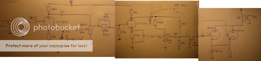
My schematic came so far by now(lower it is)
I am aiming to get that early blues sound.
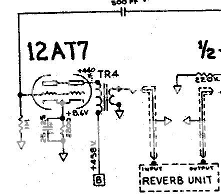
I got 24k/8ohm/2W output transformer which is almost like the one Fender used in reverb units (23k/8ohm/3.5W).
They used parallel SE design:
So there is loadline for each half:
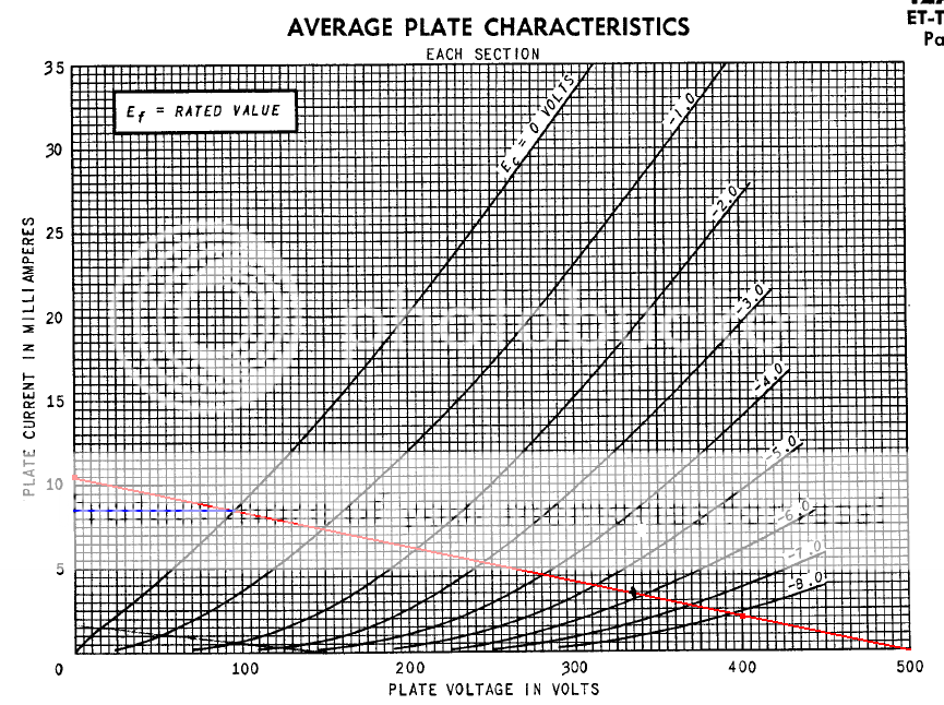
I am probably going to use 200V B+, so my calculatoins got like this:
From graph I get 6.5mA per stage, so togheter 13mA and -2V on grid. So I would need 154 ohm resistor(not marked value on schematic I suppose it would get 0,3W output power.(Ia*Ua/8) and 0.8W of dissipation.
But how could I get a little more power out of it? Can it be done? I would like at least 0.5W if possible.
I am going to use 8' ,8 ohm, 15W speaker.
Also check component values on the schematic, suggestions are welcome. This is my first design of an amp. (But I already built one 5W SE with el84)

I am aiming to get that early blues sound.
I got 24k/8ohm/2W output transformer which is almost like the one Fender used in reverb units (23k/8ohm/3.5W).
They used parallel SE design:
So there is loadline for each half:
I am probably going to use 200V B+, so my calculatoins got like this:
From graph I get 6.5mA per stage, so togheter 13mA and -2V on grid. So I would need 154 ohm resistor(not marked value on schematic I suppose it would get 0,3W output power.(Ia*Ua/8) and 0.8W of dissipation.
But how could I get a little more power out of it? Can it be done? I would like at least 0.5W if possible.
I am going to use 8' ,8 ohm, 15W speaker.
Also check component values on the schematic, suggestions are welcome. This is my first design of an amp. (But I already built one 5W SE with el84)
Check out the The Hundred-Buck Amp ChallengeMore power? Try operating the 12AT7 in push-pull. Yeah, it would need a PI stage, but it would make the whole thing even more unique!
Dave
http://www.diyaudio.com/forums/instruments-amps/190738-hundred-buck-amp-challenge.html
You could run in push-pull in a self-split arrangement. I did one version of my amp with it but with 6AQ5's. Another amp used 6AU5's I think, about the same power level as yours. I used a 70V audio matching transformer, think his was a 100V. You could add a PI stage. Come visit, looks like your amp would fit right in.
Now I decided to dump at7 as power tube and run ecc99 in push pull mode. For better performance
A wise choice I think....
There's a few double-triodes like the 7119, 5687 and my personal favorate, the 7044 that should do well for your amp as well...
")
Mine is using 6N1P tubes in P-P with the triodes in each tube paralleled. Should be about 3 watts of power.
That should be very interesting!
Do you have any sound samples?
How do you calculate in this case what primary side of transformer is needed?
No sound samples yet - I'm still in the testing stage. Maybe this weekend I can get some time to work on it.
How I calculate the transformer:
Look at your load line and figure out where you want to operate. For me, I've got a 300v B+ and a maximum of 2.2 Watts dissipation per triode. I decided to run at half B+ (150v) and 10ma for 1.5w dissipation at idle. Ohms law tells me that I would need an equivalent 15K resistor to drop 150v at 10ma. For a Push-pull amp the impedance will be double that from plate to plate. But since I'm running two triodes per tube in parallel, that halves the impedance (because there's twice the current).
I'll assume an 8 ohm speaker. Now we have a ratio of 15K:8 ohms needed across the transformer. That's a 1875:1 ratio. In a normal output transformer you would look for a 15K ohm rated primary, or a 7.5K primary with a 4 ohm tap to preserve the ratio. I like to use power torroids as OPTs since they're inexpensive and have high bandwidth. To figure out what power transformer to use, take the square root of the impedance ratio (impedance ratio is the square of the voltage ratio) and you get a 43.3:1 voltage ratio. Using a 240 volt transformer (two 120v windings), divide 240 by 43.3 and you get 5.54. So I use a 5v transformer.
If you are running 300V B+ at 10mA wont you have near 295V anode to cathode since the only plate load is an inductor and the IR loss will be fairly low.
Even with 200 Ohm DCr you would only have .010A*200 ohm = 2V. Figure a bias point near 1V and you only have 3V drop and 297V a-k.
Even with 200 Ohm DCr you would only have .010A*200 ohm = 2V. Figure a bias point near 1V and you only have 3V drop and 297V a-k.
- Status
- This old topic is closed. If you want to reopen this topic, contact a moderator using the "Report Post" button.
- Home
- Live Sound
- Instruments and Amps
- help me designing parallel SE guitar amp with 12at7 as power tube