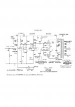
I have started a project build based on ECL82 tubes. I´ve decided to go for a class AB push pull design. This is my first attempt to design my own amp.
I got parts from an old philips radio with a dead transformer and a 8 ohm speaker element that I had laying around.
Now i´m in the process of rewinding the transformer and designing the amp. I have chosen an ht+ of 250 VDC. The purpose of this amp is to learn about tube amps and get a small rehearsal amp.
The preamp consist of one triode section, and is then followed by a cathodyne phase inverter (the other triode).
The problems that i now am having are the coulings between stages (high-pass filters?), the biasing part of the power stage and the value of the grid-stoppers.
Any ideas, comments or other thoughts?
Coupling: use simple 0.1uF 300V or higher MKP caps; upgrade if you see the need to, but there's no reason to spend an arm and a leg at this point. You could also consider DC coupling, but as a first build, I'd stick to using coupling caps.
Power stage bias: simple resistor (bypassed with a 150uF or bigger cap for better low-freq response) bias does nicely for an application like this. Decide on an operating point using the curves for the pentode section of the PCL and then calculate bias resistor accordingly. There are many online tutorials for this.
Grid stoppers: just use 1k and be done with it, or spend hours and hours over-complicating things. Choice is yours.
Since this is your first build and not hi-fi, I'd go for the tried and tested solutions as outlined above.
Yeah, why not, but keep in mind that the tone stack is going to absorb any gain created in earlier stages, so it won't give much in the way of overdrive or distortion. You could always put an extra ecc83/12ax7 or some other high-gain triode up front and use that for distortion if necessary. Or perhaps even do something with two diodes and some signal shaping for real metal distortion, but only if you're into that stuffOk, thanks for the clarifications.
I was a little worried about little gain, and my backup solution is to use both triode sections in a gain stage with tone stack in between, and a ecc85 as a long tail pair. Is this possible?
")
The initial plan will work just fine for reasonably clean and slightly warm playing.
I think i will put it together using my initial plan, but leave space for additional tube sockets etc. when i make the chassis. Now i only need to get my transformer winded (maybe oversize it a little for future needs) and check if the OT from the radio is useable for this project.
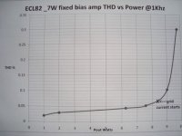
Nice simply start with ECL82.. I wasn't disappointed....and was suprised how loud this amp sounded..I also did the Mullard variant and found the thd & s/n ratios too high, especially when the output was via a Lpad ideal for headphones etc. So out of the junk box I came up with a fixed bias variant which offered a nice o/p for easy listening HiFi and a practice guitar amp.
The quality is astounding, mainly due to a good o/p transformer the Sowter UO67.
I found the ECL82 triode sections disappointing to use......hard to linearise and optimise for lowest thd considering this tube was really designated in cheap B/W TV sound stages. So the triode sections in this amp is redundant and since I have alot of 12GN7's, I used this instead but others would equally work. The ECC88 both sections in parallel configurated as concertina provide the easy low Z drive levels.
O/p stage quiescent each tube 31mA for lowest thd. Take note o/p stage UL snubbers.
Happy listening!
richy
Attachments
Ok, another question regarding OT:s
The speaker element that i intend to use is 8 ohm, but I´m thinking of making it a top with a separate cabinet. That means 4, 8 and 16 ohm taps. From what i´ve read, the OT reflects the speaker load to the tubes.
The following info is from the datasheet (operating characteristics, class AB):
Vba : 250 V
Vbg2: 200 V
Rk: 220 Ohm (common cathode resistor)
Raa´: 10 kohm
Vi: 0 12,5 Veff
Ia: 2 x 28 2 x 31 mA
Ig2: 2 x 5,8 2 x 13 mA
Wo: 0 10,5 W
dtot: - 4,8 %
I assume that the Raa´ value (10k) is anode to anode resistance.
Does this mean that the 8 ohm speaker element on the secondary should be reflected to 10k?
Not resistance, but impedance. But you're on the right track.I assume that the Raa´ value (10k) is anode to anode resistance.
Yes. There are many docs (also online) that explain how to calculate with transformer impedance, voltage and turns ratios. E.g. here: Output Transformer ImpedanceDoes this mean that the 8 ohm speaker element on the secondary should be reflected to 10k?
But low power 10k:8Ohm PP output transformers are just about the most common kind; anything suited for 2xEL84/6BQ5 in PP will work.
- Status
- This old topic is closed. If you want to reopen this topic, contact a moderator using the "Report Post" button.
- Home
- Live Sound
- Instruments and Amps
- ECL82 pp guitar amp project