Hi, quite new here so not sure where to post. Mods, feel free to move this ")
I've designed (if you can call ripping off two things from other people and sticking them together "designing") a guitar effects pedal for a university project. The circuit is very simple - just a buffer and a high-pass filter. I built the thing, but it's not working! When I engage the pedal, I get no sound. At all.
I know how to do true bypass switching so I've left that out of the schematic. I'm quite new to electronics, but I read a lot, haha. I've tried to write out the schematic as literally as possible. I forgot to write the op-amp power supply connections - these literally connect straight to the battery, right? Or do I need to add additional stuff there to make it work?
The buffer is from muzique.com, the filter circuit itself I forget where I got it - probably Art of Electronics. It's a standard Sallen-Key in any case. The op-amp is a 4558 (had a bunch lying around).
Could you geniuses please have a look at my schematic and inform me if there's something wrong with it? I know troubleshooting is a difficult process, so I want to know where to look - if I know my schematic is perfect then obviously the problem lies in construction. Sorry about the lame picture, I literally photographed it from my notebook!
Thanks so much guys! Quick replies would be highly appreciated as I have to hand this in on Thursday.
I've designed (if you can call ripping off two things from other people and sticking them together "designing") a guitar effects pedal for a university project. The circuit is very simple - just a buffer and a high-pass filter. I built the thing, but it's not working!
When I engage the pedal, I get no sound. At all.I know how to do true bypass switching so I've left that out of the schematic. I'm quite new to electronics, but I read a lot, haha. I've tried to write out the schematic as literally as possible. I forgot to write the op-amp power supply connections - these literally connect straight to the battery, right? Or do I need to add additional stuff there to make it work?
The buffer is from muzique.com, the filter circuit itself I forget where I got it - probably Art of Electronics. It's a standard Sallen-Key in any case. The op-amp is a 4558 (had a bunch lying around).
Could you geniuses please have a look at my schematic and inform me if there's something wrong with it? I know troubleshooting is a difficult process, so I want to know where to look - if I know my schematic is perfect then obviously the problem lies in construction. Sorry about the lame picture, I literally photographed it from my notebook!
Thanks so much guys! Quick replies would be highly appreciated as I have to hand this in on Thursday.
Attachments
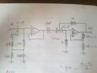
There are a Lot of problems with this curcuit , The first stage seems okay but the Opamp should be a Fet input opamp because of the 1m input impedance .... the output of the First stage has a 10uf and a 470uF in series , get rid of the 10uF as it isn"t needed .......
The Values of the second stage filter don"t seem right but I haven"t taken the time to calculate .....
the second Stage isn"t biased so it won"t work , the way you have it , it would work with a Dual PSU but not with a single supply , you need to Bias the input to 1/2 supply like the first stage , the second stage will also need an ouput cap with a single supply ......
Cheers
- Status
- This old topic is closed. If you want to reopen this topic, contact a moderator using the "Report Post" button.