Look...u have two 9volt batteries right? So why bother using a single polarity and have to include both input and output capacitors as well as the voltage dividers?
Connect the batteries so u have + and - 9volts, and then u can direct couple the buffer, as well as use less resistors.
Connect the batteries so u have + and - 9volts, and then u can direct couple the buffer, as well as use less resistors.
Look...u have two 9volt batteries right? So why bother using a single polarity and have to include both input and output capacitors as well as the voltage dividers?
Connect the batteries so u have + and - 9volts, and then u can direct couple the buffer, as well as use less resistors.
You will need to make sure to replace both batteries at the same time, and be sure about equal "freshness". Also, it is a bit harder to switch the onboard electronics on and off with a bipolair PSU. I would just stack them and use a nice output cap, easy to switch with a stereo jack, never run the risk of having DC on the output.
True, except the input will always be at ground level in my circuit, so no input cap or resistor divider needed. The output would need an output cap, which is always good either way for protection at both ends.
The switch can be a double throw, no real problem.
The switch can be a double throw, no real problem.
Last edited:
Actually, most onboard electronics are switched by using a stereo jack chassis. Signal ground is ground contact, battery ground is the ring contact. Plug in a mono jack --> preamp on. Unplug it --> preamp off
If you use a switch, you run the risk of forgetting it or it being knocked when the guitar is in the gig bag, and ending up on stage with empty batteries. there are some exotic chassis which have switching (but not double pole, I think), and you could envision something using fancy switching with transistors. But IMHO that's more hassle than it's worth, to eliminate two resistors (three if done properly).
If you use a switch, you run the risk of forgetting it or it being knocked when the guitar is in the gig bag, and ending up on stage with empty batteries. there are some exotic chassis which have switching (but not double pole, I think), and you could envision something using fancy switching with transistors. But IMHO that's more hassle than it's worth, to eliminate two resistors (three if done properly).
mjf,hello paul.
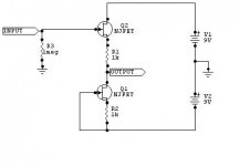
so here is a minimalistic schematic of the buffer amp. i left out the big elcos because it should fit into the body of your guitar.
psu is two 9v batteries in series..........
the foto shows the circuit on perfboard,i used spareparts which i had on hand.
greetings
If I am to build a buffer pre base on this minimalistic schematic, can i use a 18VDC wallwart instead of 2 9v batteries - do i need to increase the 47uf to a larger value to say 500uf . Also how would i go about install a volume pot to it.
How does this design sound, are you happy with it. Thanks.
mjf,
If I am to build a buffer pre base on this minimalistic schematic, can i use a 18VDC wallwart instead of 2 9v batteries - do i need to increase the 47uf to a larger value to say 500uf . Also how would i go about install a volume pot to it.
How does this design sound, are you happy with it. Thanks.
If you are using a wallwart as a power supply I am assuming you are installing this in a box. If so you can use a bigger cap. I would use a 10,000uF cap and a 1 to 3 Ohm 3 watt resistor as pictured in the diagram. The cap value isn't critical, but the bigger the better.
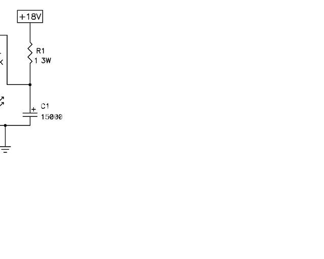
If the wallwart is still noisy you can make a voltage regulator that will kill all the noise. You'll have to substitute the L7812CV for a L7818CV to run at 18 volts.
An externally hosted image should be here but it was not working when we last tested it.
An externally hosted image should be here but it was not working when we last tested it.
You can put a linear 50K volume pot between the input and 1K resistor.
when you buy the parts make sure the 2SK170's are matched. good luck!
QUOTE
If I am to build a buffer pre base on this minimalistic schematic, can i use a 18VDC wallwart instead of 2 9v batteries ........
- yes,but it should not be too noisy as paul mentioned.
do i need to increase the 47uf to a larger value to say 500uf .
- you must not, but you can if you want to have better noise filtering (is always a good thing!).
Also how would i go about install a volume pot to it.
- at the input i would use a pot value around 1 meg ohm,because a guitar needs a high input impedance (typically 500k.......1meg).at the output it can be lower,may say 50k.......100k.
How does this design sound, are you happy with it.
- perhaps you should ask paul and others, i am only a technician,not a musician.")
greetings
If I am to build a buffer pre base on this minimalistic schematic, can i use a 18VDC wallwart instead of 2 9v batteries ........
- yes,but it should not be too noisy as paul mentioned.
do i need to increase the 47uf to a larger value to say 500uf .
- you must not, but you can if you want to have better noise filtering (is always a good thing!).
Also how would i go about install a volume pot to it.
- at the input i would use a pot value around 1 meg ohm,because a guitar needs a high input impedance (typically 500k.......1meg).at the output it can be lower,may say 50k.......100k.
How does this design sound, are you happy with it.
- perhaps you should ask paul and others, i am only a technician,not a musician.
greetings
Maybe your pickups are too close to your strings?
I already solved that problem
- Status
- This old topic is closed. If you want to reopen this topic, contact a moderator using the "Report Post" button.
- Home
- Live Sound
- Instruments and Amps
- JFET bass preamp clipping problem