Hi, I have designed a four channel guitar amp and was wondering if somebody could advise me how to implement the switching of channels from the front panel.
I have a load of relays to use and have worked out which relays would need to be on and off for each channel, but I'm not sure how to give each relay the required voltage (5v) from some kind of switch without shorting the other channels.
e.g if channel one needs relays 1 and 2 to be on and channel two needs relays 1, 2, 3 and 4 to be on, then if all were connected to a rotary or toggle switch, if i'm not mistaken only channel two would operate due to shorting. The concept here is to connect one position of a rotary switch to relays one and two, and the second position of the switch to relays 1-4.
There is possibilities of programming a pic to do the work but i've never used these and have a deadline approaching fast so don't fancy learning something new! Does anybody have any other ideas?
Thanks
There are many ways to achieve what you want. The best thing is for you to look at what others have done.
Here is an example of an amp with 6 channel switching including relay drives, J-FET switching etc., Note that where a relay needs to be active on 2 or more channel selections then "Diode OR" logic function is used:
http://www.schematicheaven.com/newamps/hk_triamp.pdf
You could also view some of the other schematics at that site. This one maybe of interest as well. Trace Elliot generally do their entire channel switching with relays:
http://www.schematicheaven.com/newamps/trace_elliot_trident_c100_h100.pdf
Browse that site for further ideas - but those 2 should get you started.
The Hughes and Kettner is quite clever in that channel selection is done by a momentary switch to ground on any of the 6 channel select lines (See page 9). This can be done via front panel switches or footswitches. Note the smaller capacitor value on the base of the Channel 1A select transistor. That ensures that Channel1A is selected at power on.
The Trace Elliot arrangement is simpler.
Hope this is useful,
Cheers,
Ian
Thanks a lot! I think I was heading in that direction but those circuits have definately helped. I was planning on using momentary switches going into SR latches and isolating them from each other using diodes for the front panel. The diode technique should work for other side of the SR latch going to the relays. I'll compare with those circuits you pointed out and see where I end up!
Yeah, the most straightforwaqrd way is to connect each output position on your rotary switch to each of the relays required for that channel via a diode per relay.
Say, position 1 connects to relays 1 and 2 via 2 diodes, 2 to 1, 2, 3 and 4 via 4 diodes. Obviously the diodes all have to point in the same direction and the direction depends on whether the wiper of the rotary switch is connected to the relay supply +ve or -ve. Each output position now activates the required relays without backfeeding the others through the common connections at the switch. Each relay is now a hardwired OR gate.
You can do a lot of other things, read a pot with a PIC A/D for example, but diode logic is the least elaborate and most economical solution in this case.
w
Say, position 1 connects to relays 1 and 2 via 2 diodes, 2 to 1, 2, 3 and 4 via 4 diodes. Obviously the diodes all have to point in the same direction and the direction depends on whether the wiper of the rotary switch is connected to the relay supply +ve or -ve. Each output position now activates the required relays without backfeeding the others through the common connections at the switch. Each relay is now a hardwired OR gate.
An externally hosted image should be here but it was not working when we last tested it.
You can do a lot of other things, read a pot with a PIC A/D for example, but diode logic is the least elaborate and most economical solution in this case.
w
Re: Re: Channel Switching
Hi
1) Don't forget each relay coil needs a freewheeling diode for reverse voltage spike protection.http://www.kpsec.freeuk.com/components/relay.htm#protect
2) Consider using a common + supply connection to the relays instead of ground. (less likely to short out the supply as it is routed around much less) Reverse all diodes.
3) How about a indicator LED in series with each coil. May adjust supply, but coils have a wide range of pull-in current.
wakibaki said:
Each relay is now a hardwired OR gate.
An externally hosted image should be here but it was not working when we last tested it.
but diode logic is the least elaborate and most economical solution in this case.
w
Hi
1) Don't forget each relay coil needs a freewheeling diode for reverse voltage spike protection.http://www.kpsec.freeuk.com/components/relay.htm#protect
2) Consider using a common + supply connection to the relays instead of ground. (less likely to short out the supply as it is routed around much less) Reverse all diodes.
3) How about a indicator LED in series with each coil. May adjust supply, but coils have a wide range of pull-in current.

Hello again- I'm having to resurrect this thread again because I'm having problems still! The concepts shown to me earlier make good sense but I'm beginning to realise that the 10 5V relays I have are going to draw quite a lot of current which I don't really have available.
I have got plenty of surpluss current left over in the heater supply (about 4A worth) but I don't really fancy using that because as far as I'm aware i would have to rectify after the input valve which is going to send more current past the input valve and potentially induce noise.
The bias supply is 50V 0.1A so that is too low current. I was wondering if anybody had any ideas of what I could do here. I was thinking of using the CMOS chips which appear to be a direct replacement for relays.
Thanks
TEN 5V relays?
You'll have to post a diagram of the system, or at least specify the signal levels that the 'relays' are switching.
At the moment I can't tell, maybe one is switching the signal at the input, another one is switching power to a module. The power handling required is critical in the selection of solid-state switching.
I like relays in a valve guitar amp. Nice electro-mechanical things. You can get some very small low-power ones. I've got one here - surface mount - Omron G6J-2FS-Y. 30mA in a 5V version. It's 11x6x9h (mm).
10 of these would be 300mA, not a lot of current to pull past your input valve, the additional noise is probably barely audible, if at all. You can test that out fairly simply anyway by just loading up the heater supply temporarily.
You can also mitigate the current draw somewhat with a slightly more sophisticated driver as the holding current is less than the pull-in current, but I'd just be tempted to drive them from a small auxiliary transformer. If you build it this way with the diodes and relays, any half-smart engineer looking at it later will know how it works and you'll always be able to get the parts. Have a look at Rod Elliott's site - the soft-start circuit has some ideas on driving relays.
w
Hi, the relays are all just routing the guitar signal so any relay should do the job. I have ordered a load of goodsky 5v ones from banzai music. The idea of loading up the heater chain is a good idea so i'll try that and see how noise is affected. Most designs ive seen use transistors to drive the relays - will this keep the current draw down? I have considered an auxilary transformer but have very little space left in the chassis - if i find one small enough then that would probably be the best bet.
For channel 4 all 10 relays are on, or if its wired the other way round then channel 1 will have all 10 on. What you describe there is seeming to be the best method - I've noticed a lot of amps restify after the heaters so it can't be that bad! What do you think about driving each relay with a transister - useful or pointless?
AmpBuilder225 said:What do you think about driving each relay with a transister - useful or pointless?
It might.. depends on your switch logic, but it won't save the total relay current, just lowers the control switch current. I can't imagine all relays on, care to share ? Maybe with the collective brainpower here, they can help simplify the switching diagram/logic...
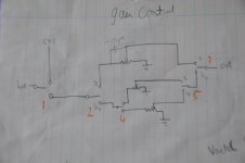
I'll attach the photo's in two separate posts. Relays 6 and 7 just tap off from the preamp at different points. Apologies for the poor drawings - the volume and gain controls are also wrong so ignore them!
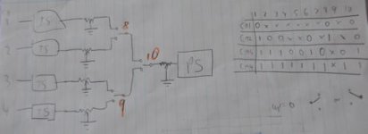
The image on this page adjusts the gain for each distorted channel or taps off to ch1. The second image is for the other end of the circuit to select which channel is going to the phase splitter.
On the right of the second image is a truth table to show which relays need to be on for which channel to be active
Attachments
AmpBuilder225 said:Yeh - That sounds like a good idea. Is this the same point you made earlier about using a common +ve rail?
No that was just sound engineering practical advice>
That point depends on if the control circuit supply is grounded or not, and it seems unlikely if you are using the heater rectified.
Invert by switching all relays NO and NC positions.
Would it not be possible to eliminate the relayes and use LDRs or FETs to shunt the OFF signals to ground? http://www.freewebs.com/valvewizard2/ChannelSwitcher.jpg
That was my original idea actually but the LDR's seemed quite pricey and I wasn't entirely sure how to make them operate in the same way as a SPDT relay. I might try looking into it again. Presumably they use negligable current because there's no mechanical function to them?
- Status
- This old topic is closed. If you want to reopen this topic, contact a moderator using the "Report Post" button.
- Home
- Live Sound
- Instruments and Amps
- Channel Switching