I've done some experiments on a preamp design that is fed by a weak signal such as the signal from a guitar pickup.
I've tried this approach, http://sound.westhost.com/p87-f1.gif but what I really would like is a modification with ultra high input impedance. One could think of omitting the 10k input resistors but that wrecks its operation since the inputs of the op's need some bias current.
My version has an extra inverter on the output in case one want balanced output as well. the R7 resistor is replaced by a pot and allows me to adjust the gain.
Many thanks in advance.
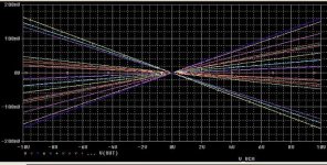
Simulation says ....
That circuit has pretty good CMRR. Unmatched 1% resistors, shown below, give about 36dB CMRR. Matching to 0.1% gives 56dB CMRR.
I don't know too much about guitar amps, most of the circuits I saw so far had 100k or so ZIN.
Resistors R1 and R2 can be virtually any value, as they do not affect the gain. You could increase them to 100k and beyond. This might make the system noisier, though due to the resistor noise. Give it a try.
Attachments
I've successfully tried to omit R1 completely and this appears to work for some reason. The advantage with this is that the source doesn't see and load. This should have a bad impact on the CMRR figure shouldn't it at least theoretically? I've found out that I could choose R2 pretty big to diminish the sacrifice of symmetry. Is this a good idea?
I'm soon about to design a low-profile layout on this. Would be nice to find a device with extremely low input noise. Not so many dual opamps have extremely low noise figures like the single INA217 for example. With popular op's such as the TL072 the circuit behaves good but with a low noise supersonic device such as THS6062 there's a lot of hiss coming from the setup. I want this preamp to be premium audiophile quality.
I'm soon about to design a low-profile layout on this. Would be nice to find a device with extremely low input noise. Not so many dual opamps have extremely low noise figures like the single INA217 for example. With popular op's such as the TL072 the circuit behaves good but with a low noise supersonic device such as THS6062 there's a lot of hiss coming from the setup. I want this preamp to be premium audiophile quality.
Actually I'm not too concerned about the op amps internal input impedance but rather the circuit I'm using. I guess they all need some amount of bias current into the input either through a resistor or through source.
I've come this far with the design, http://www.carmi.se/misterstarshine/img/bal_preamp_schem.png
I wonder if the THS6062's are a good alternative under the condition that one manage to make them work in the layout. They are high-bandwidth devices but the noise figure and THD are superior. I haven't managed to make the design work well with the THS6062's on the breadboard though.
I'll soon post a layout proposal for the design. I'm pretty happy with the design tbh.
I want to point out that the circuit is pretty common and I've nicked it and modified it.
MisterStarshine said:Actually I'm not too concerned about the op amps internal input impedance but rather the circuit I'm using.
This makes no sense to me. What is the point of playing around with resistor values if that effect is completely negated by the opamp's internals?
IMHO, omitting R1 is a big no no. One reason it is there is to terminate the input so that there is no oscillation when the input is unplugged.
MisterStarshine said:I want to point out that the circuit is pretty common and I've nicked it and modified it.
I don't want to make it sound like I'm trying to pick on you, after all you should and will wind up doing whatever you want, but I have to say that your circuit is not common at all in any way for a guitar preamp. You mentioned Rod Elliot, so look at how he builds a guitar preamp:
An externally hosted image should be here but it was not working when we last tested it.
Could be my mistake but I thought most op amps had several mega ohms input impedance when run in non-inverting mode.
Anyway, it's most likely to be a good idea to keep them. I hope I'll be able to use this design with high bandwidth op amps. This design could very well be used in any application.
Here are my schematic and board:
http://www.carmi.se/misterstarshine/img/bal_preamp_schem.png
http://www.carmi.se/misterstarshine/img/bal_preamp_brd.png
The board is slightly bigger than a square inch. I'm about to attempt to make some prototypes. This design should be totally perfect for all high-end audio purposes. If it will prove necessary I will have to adjust it in case it would prove not to work with 100MHz op amps.
Maybe I should've pointed out that "my" design is optimized for use with a computer. It's supposed to have pretty low impedance output and high impedance input.
What's fancy with my design is that it incorporates the concept of balanced audio which has proven to have big impact on hum rejection in my environment.
I never meant to imply that my circuit would be common in guitar contexts. This is in fact an experiment and what I've also done without being aware of it is that I've taken a mic preamp design and made it high impedance input to suit any signal source.
MisterStarshine said:Could be my mistake but I thought most op amps had several mega ohms input impedance when run in non-inverting mode.
Actually, that's not true at all, but I found something funny when looking at the TL072 datasheet....it is a JFET input opamp. Well that explains why Rod Elliot uses them for guitar preamps!

So I looked up the spec for the NE5532 that you are using. Datasheet says input resistance is 300K typical but only 30K minimum. Not good.
Yeah, you're totally right. Had to check datasheet for NE5532 to believe it.
I'm lucky that the THS6062's that I plan to use are stated 2 mega ohm input resistance.
I've performed an etching of the board now. Wish me luck.
http://www.carmi.se/misterstarshine/img/etch.png
I don't know if there are many high input impedance balanced preamps out there that are only slightly bigger than a square inch.
The size could be reduced further if industrial production methods are available.
The future will judge if this concept will prove useful. I've got pretty high expectations.
Mister Sunshine,
It's a very nice project but I cannot understand how are you going to connect a guitar to the preamp. Having balanced output makes sense and it's clear. But how a guitar will be connected to IN+ and IN- inputs? Usually guitars have unbalanced output. Can you clarify this?
Mark
It's a very nice project but I cannot understand how are you going to connect a guitar to the preamp. Having balanced output makes sense and it's clear. But how a guitar will be connected to IN+ and IN- inputs? Usually guitars have unbalanced output. Can you clarify this?
Mark
I still don't get it. "Hot" wire from pickup will be connected to VIN+, "Ground" to ground. And what will be connected to VIN-? I've seen similar preamps (especially in bass guitars) but they had unbalanced input and balanced output. In your case both the input and output are balanced. Hence my question how you are going to wire it.
Anyway, good luck - I see you are very close to finish it. Let us know what are the results.
Mark
Anyway, good luck - I see you are very close to finish it. Let us know what are the results.
Mark
If your pickup has it's shield (if shielded) connected to one of the terminals internally then you will be forced to use it in single ended mode. Else just connect pickup terminals over Vin+ and Vin- and shield to ground.
If one really wants single ended input to the preamp I guess that can be arranged by just shorting Vin- to ground. At least I hope so.
However, many pickups are unshielded and lacks the shield connector of course. In that case just connect Vin- to one of the terminals on pickup and Vin+ to the other.
MisterStarshine said:However, many pickups are unshielded and lacks the shield connector of course. In that case just connect Vin- to one of the terminals on pickup and Vin+ to the other.
That won't work very well. I hate to say this, but it sounds like you really have no idea what you are doing. You are right in thinking that a pickup is inherently balanced. However, everything else that is standard in the guitar world isn't. A standard 1/4" guitar cord is unbalanced. So if you plug that into a balanced preamp you will get MORE hum. I hate to rain on your parade but I think the best thing for you is to build some conventional circuits designed by knowledgeable people before you venture out into designing your own applications.
It's very well possible that you're right. This is somewhat experimental but is based on some tests I've done.
This concept is anything but standard. A well designed system would have balanced input and output as additional options rather than hardwired. One could even consider to have an xlr for the balanced option to inhibit the user to make mistakes about this. At least good labelling.
A balanced system can be used as single ended but not the other way around.
Besides, many humbuckers have centertaps and can be wired to operate in balanced mode.
A site called Naiant Studio has some information on balancing in guitar applications, http://naiant.com/guitarwiring.html
My own tests confirm the statements in the Naiant Studio site.
MisterStarshine said:Besides, many humbuckers have centertaps and can be wired to operate in balanced mode.
OK, you missed my point, and Naiant's as well. Look at the schematic on the link you sent. (1) The guitar internal wiring is not standard, (2) they mention the use of a stereo cable instead of a standard guitar cord, and (3) the pickup is not centertapped since it doesn't need to be. If you wire up your guitar like that, use a stereo cord, and hook it up to a balanced preamp, then yes you have a chance at getting a quieter signal. If you don't do all those things, you are making everything worse.
In the couple inches between the pickup and your little preamp circuit, balanced or not is going to make very little difference. We use balanced lines for things like mic cords so we can run the tiny mic signal across the stage without picking up tons of noise. But inside the little innards hatch of a guitar, which OUGHT to be shielded anyway, I don't see the advantage.
- Status
- This old topic is closed. If you want to reopen this topic, contact a moderator using the "Report Post" button.
- Home
- Live Sound
- Instruments and Amps
- Guitar pickup balanced preamp