steenoe said:Hi again Mullard, you are welcomeJust for the record; I have to be a little bit against your saying that Marcello's amp is Aleph based. It is not
It is Zen based, with an Aleph based CCS
Steen
Steen,
Good points. For me, if it has an Aleph current-source providing Class-A bias to a common-source MOSFET output device, I tend to regard it as an Aleph design.
The original Aleph amplifiers and the follow-on XA amplifiers simply insert alternative front-end circuits on a common output-stage design, while the 'Zen' designs inject the input signal directly into a 'naked' output stage. So, I can see where confusion could result from indiscriminate use of the 'Aleph' and 'Zen' labels. I'll be more circumspect in my use of these terms in the future.
A future design project for me is an XA-based headphone-amplifier. I've already modified a set of Grado's and a set of Sennheiser's for balanced-drive operations (separating the usual common headphone 'ground' into separte returns for each 'can', then soldering-on the XLR connectors), along with a perf-board XA headphone-amp prototype to drive them (which throws off about 25-30 watts of heat, just to drive headphones...). When I get some 'spare time' (in about a couple of months), I'm going to replace the high-bias power MOSFET-based differential input stage with a paralleled 6N1P-based vacuum-tube differential input stage; the sound should be glorious. With the high-current needs of the 6N1P heaters, total power dissapation will be somewhere between 80-100 watts. I just love the smell of burnin' silicon grease in the mornin'...
That would be greatA future design project for me is an XA-based headphone-amplifier.
Please dont hesitate to implement a J-fet input Which should be easy enough, considering the railvoltages needed for headphone amp?Steen
BTW Better get some of those J-fets that papa fancies
This is cut from another thread2SK370 and 2SJ108, readily available from Toshiba.
paulb, just what I was thinking Having been listening to the "tortello" amp through my headphones for a few years, I cant claim to miss/need anything! I slightly tweeked it for higher impedance phones, as far as I recall. Mine are Beyerdynamics 880's. But whatever, I am open to new ideas, so if anyone posts a nice circuit (especially with LU's ) I am all set to go!
Steen
BTW I still think that if anyone wants to start a J-fet design, it should have its own thread
Having been listening to the "tortello" amp through my headphones for a few years, I cant claim to miss/need anything! I slightly tweeked it for higher impedance phones, as far as I recall. Mine are Beyerdynamics 880's. But whatever, I am open to new ideas, so if anyone posts a nice circuit (especially with LU's ) I am all set to go!Steen
BTW I still think that if anyone wants to start a J-fet design, it should have its own thread
GRollins said:If a picture's worth a thousand words, surely a schematic is worth at least five hundred.
I tried recently to describe a headphone amplifier, using only words. While it is possible, in principle, to unambiguously define all the parts of a circuit and how they fit together, it's pretty cumbersome. In an attempt to clear some of the fog, I dredged up the schematic.
It's a trivial circuit, something you can build using only junk box parts, but it performs very well, indeed.
Grey
Grey,
I just got some HD555s and I was just about to build a circuit much like this. Except for thinking about taking a page from the zen-lite book and use a bulb for R4...
Question: You direct-coupled the input, so are you assuming no dc offset coming in the input? no big deal. But I ask because you bias the gate to GND so Vsource sits around -4V. This sets the polarity of the 1000uF cap with + at the output. But if you ever drove more than 4V peak of signal (it can easily happen on higher impedance cans), wouldn't this drive the cap against it's polarity? What are your thoughts on this? I don't really know how electrolytics response in reverse polarity. I've heard you can run them back to back as well for this type of situation.
You could single-end the power supply and add an input cap to the mix but that's another cap in the signal path.
--
Danny
Re: FYI: existing Aleph-based headphone-amp design
The thread has run along pretty quickly since the last time I was able to look in. I'll try to catch up.
Patrick,
A couple of thoughts:
--You might want to ground reference the input. Don't fret, I forgot to list the same resistor when I was describing this circuit in print.
--How's the DC at the output and is it thermally stable?
--I was struck by the fact that the DN2540 appears to be a depletion mode device. Why not try one as the cascode, with the Gate tied around the LU1014D to the output node?
'Just a Szekeres amp?' Well, I guess so, if you also feel that an Aleph is a Zen, or that a Krell is a Mark Levinson...the circuit is called a Source follower. It's one of the oldest circuit elements in existence. It is a rather obvious choice for a headphone amp, given that many headphones don't require additional voltage swing, only some additional current. I certainly don't claim the circuit, and haven't given it any cute names.
The three devices in the headphone circuit you linked to will need to track together thermally. If any one of the three drifts significantly, you could see some DC on your headphones' voice coils. The results wouldn't be pretty.
People have done Aleph-based headphone circuits many times. I seem to recall another round (certainly not the first) of such suggestions after the Mini-A was posted. Although the Alephs sound very good, I didn't need any voltage gain. I wasn't convinced that it was worth the fifty or seventy-five extra parts just to get rid of the output cap.
I'm also unconvinced that a low Zout is the cause of dry and sterile sound. I would suggest that it's the negative feedback necessary to create such low output impedances that causes the problem. Lower the feedback and the sterile sound will go away.
Paul,
My view on the cap question is this: Yes, there are two caps on the power supply rails, but at any given moment, the signal is only going through one of the two, depending on whether it's positive or negative relative to ground. The signal is only going to ground, not to the opposing rail. The Szekeres circuit thus has three--one at the input, one at the output, and the power supply cap. The simple follower has only two, the output cap, and one power supply cap at a time; Granted, this is perilously close to a semantic question. I can see people arguing this for thirty pages the way they do over zero feedback amps.
If the thread trends that way, I'm going to need something more refreshing than water to drink.
Danny,
A light bulb would work just fine and look cool, too. Let me know what lightbulb you use.
As far as the headphones are concerned, DC is a non-issue. The cap stops it at the output.
If you want to use a non-polarized cap, by all means do so.
Using a single-ended power supply would also require a separate bias circuit, although it need not be complicated. See the circuit Paul mentioned for one example. Another option would be a Zener at the Gate, biased by a resistor or, if you wanted to get fancy, a current source.
Grey
The thread has run along pretty quickly since the last time I was able to look in. I'll try to catch up.
EUVL said:OK, I stick my neck out and fire the first shot.
Patrick
Patrick,
A couple of thoughts:
--You might want to ground reference the input. Don't fret, I forgot to list the same resistor when I was describing this circuit in print.
--How's the DC at the output and is it thermally stable?
--I was struck by the fact that the DN2540 appears to be a depletion mode device. Why not try one as the cascode, with the Gate tied around the LU1014D to the output node?
rjm said:The circuit posted by Grey is just a Szekeres amp...
What I found (following up Greg's suggestion) was that if you use three channels rather than two you can get rid of the output coupling capacitors as well
/R
'Just a Szekeres amp?' Well, I guess so, if you also feel that an Aleph is a Zen, or that a Krell is a Mark Levinson...the circuit is called a Source follower. It's one of the oldest circuit elements in existence. It is a rather obvious choice for a headphone amp, given that many headphones don't require additional voltage swing, only some additional current. I certainly don't claim the circuit, and haven't given it any cute names.
The three devices in the headphone circuit you linked to will need to track together thermally. If any one of the three drifts significantly, you could see some DC on your headphones' voice coils. The results wouldn't be pretty.
mullardel34 said:Grey,
Given your extensive background with the XA project (Nelson Pass-based SuperSymmetry/Aleph) and other PassLabs-based efforts, I thought that I'd note that Marcello Pellerano posted the following Aleph-based headphone-amp design a few years ago on the HeadWize project page:
The Aleph-based headphone amplifier avoids one of the major deficiencies of most high-end headphone-amp designs; over-damping of the output stage. When driven with an excessively low output impedance, most high-quality headphones present a very 'dry' and 'sterile' sonic character.
People have done Aleph-based headphone circuits many times. I seem to recall another round (certainly not the first) of such suggestions after the Mini-A was posted. Although the Alephs sound very good, I didn't need any voltage gain. I wasn't convinced that it was worth the fifty or seventy-five extra parts just to get rid of the output cap.
I'm also unconvinced that a low Zout is the cause of dry and sterile sound. I would suggest that it's the negative feedback necessary to create such low output impedances that causes the problem. Lower the feedback and the sterile sound will go away.
Paul,
My view on the cap question is this: Yes, there are two caps on the power supply rails, but at any given moment, the signal is only going through one of the two, depending on whether it's positive or negative relative to ground. The signal is only going to ground, not to the opposing rail. The Szekeres circuit thus has three--one at the input, one at the output, and the power supply cap. The simple follower has only two, the output cap, and one power supply cap at a time; Granted, this is perilously close to a semantic question. I can see people arguing this for thirty pages the way they do over zero feedback amps.
If the thread trends that way, I'm going to need something more refreshing than water to drink.
Danny,
A light bulb would work just fine and look cool, too. Let me know what lightbulb you use.
As far as the headphones are concerned, DC is a non-issue. The cap stops it at the output.
If you want to use a non-polarized cap, by all means do so.
Using a single-ended power supply would also require a separate bias circuit, although it need not be complicated. See the circuit Paul mentioned for one example. Another option would be a Zener at the Gate, biased by a resistor or, if you wanted to get fancy, a current source.
Grey
Grey,
Thanks for the suggestions.
a) Input resistor
Was too lazy to draw input pot, etc. But point taken.
b) DN2540 as cascode
Good idea, but 3 issues with that :
1. DN2540 runs out of stream at 0.5A, so one would have to reduce bias to 200mA, and increase source resistor to about 10R.
2. It has a factor of 4 less transcoductance, so load line on LU1014 would change.
3. At 200mA, Vgs is about -1.8V. A bit too low ?
c) Thermal stability
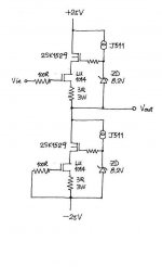
Good point, so let's do version 2 (borrowed from Mr. Curl).
A bit of a waste, but if well match should be self stabilising.
I have no headphone, so no motivation to build.
But Steen must still have enough Loveltechs. Fancy a quick mockup ?
Cheers,
Patrick
PS You may of course use IRFP240 instead of 2SK1529. You should also play around with Zener voltage to find the sweet spot for the JFET.
Thanks for the suggestions.
a) Input resistor
Was too lazy to draw input pot, etc. But point taken.
b) DN2540 as cascode
Good idea, but 3 issues with that :
1. DN2540 runs out of stream at 0.5A, so one would have to reduce bias to 200mA, and increase source resistor to about 10R.
2. It has a factor of 4 less transcoductance, so load line on LU1014 would change.
3. At 200mA, Vgs is about -1.8V. A bit too low ?
c) Thermal stability
Good point, so let's do version 2 (borrowed from Mr. Curl).
A bit of a waste, but if well match should be self stabilising.
I have no headphone, so no motivation to build.
But Steen must still have enough Loveltechs. Fancy a quick mockup ?
Cheers,
Patrick
PS You may of course use IRFP240 instead of 2SK1529. You should also play around with Zener voltage to find the sweet spot for the JFET.
Attachments
As a matter of fact, I do.But Steen must still have enough Loveltechs. Fancy a quick mockup ?
How is this for the last details? Check the values, please.
What is the output impedance of this circuit? A standard headphone expects to see around 120r.
Attachments
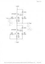
> How is this for the last details?
Looks OK.
Input resistor is probably not critical. Try 10k and 22k and see whether you hear any difference.
The gate resistor you need to try. Start with 220R if you use IRFP240. You may then try 100R and see whether you get oscillation (I doubt).
I normally use 432R with 2SK1529, which has much lower capacitance.
You might need to adjust one of the source resistor a bit (e.g. by parallel a high value 1W) to get zero offset at the ouput if the JFETs are not 100% fully matched.
Patrick
Thats not a shameShame, I missed it
I am sure many of us learned a little from that.I asked this:
What is the output impedance of this circuit? A standard headphone expects to see around 120r.
Steen
> I asked this:
Was not in your original post.
Well, I would say the output impedance would be the source resistor plus 1/Yfs for the JFET at the working point, which is about 1 ohm. So in total 4 ohms. If you what lower impedance, you could lower the source resistor to say 0.68R (a la ZV9) with corresponding increase in bias current (and heat).
Patrick
Thats right. It was the usual case of being overlooked when editing.Was not in your original post.
If the output impedance is so low and headphones build to international standards should expect 120r, wouldnt it be a good idea to put a 120r, 5watter in series with the output?
Steen
> If the output impedance is so low and headphones build to international standards should expect 120r, wouldnt it be a good idea to put a 120r, 5watter in series with the output?
Are you sure ?
I mean I saw a few audiophile headphones with around 40 ohm impedance (Sennheiser HD595, Grado SR80, .....). Surely you do not want to drive them with 120R Rout ?
Grey's circuit has even lower output impedance, IMO.
Patrick
Are you sure ?
I mean I saw a few audiophile headphones with around 40 ohm impedance (Sennheiser HD595, Grado SR80, .....). Surely you do not want to drive them with 120R Rout ?
Grey's circuit has even lower output impedance, IMO.
Patrick
> http://www.epanorama.net/circuits/headphone_attenuator.html
They argue that you should put a 120ohm in series.
This is essentially an output attenuation.
You have to remember that the follower circuit has close to unity gain.
But I think you should ask Grey. I am not into headphones at all.
Patrick
They argue that you should put a 120ohm in series.
This is essentially an output attenuation.
You have to remember that the follower circuit has close to unity gain.
But I think you should ask Grey. I am not into headphones at all.
Patrick
I am "sort of" sure.
Take a look at this: http://sound.westhost.com/project70.htm
It says that a headphone should want to see 120r, regardless of its own impedance. Its easy enough to test though, so its not a big deal. Just thought I would mention it
If someone knows, please tune in.
Steen
Take a look at this: http://sound.westhost.com/project70.htm
It says that a headphone should want to see 120r, regardless of its own impedance. Its easy enough to test though, so its not a big deal. Just thought I would mention it
If someone knows, please tune in.
Steen
- Status
- This old topic is closed. If you want to reopen this topic, contact a moderator using the "Report Post" button.
- Home
- Amplifiers
- Headphone Systems
- MOSFET follower headphone amplifier