Hey guys,
I have been using tubes for headphones for a good while, and have a pretty nice amp as of right now. But I have been really looking to make a nice amp and want to go with pretty nice stuff.
Total budget would be like $400, but I could be convinced...
I am looking to give a pretty high current, I use Audio-Technica W5000s which are 50 ohms. I am looking to also have a tube rectified PS, I think thats the right wording, and I'm wondering what yall would suggest.
Although it dosent really matter tubes that are big and look cool would always be a +!
Iv read a good bit but im still unsure of exactly waht to build. I would be cool with if there is a PS i should look at and then attach that to an amp design or somethign.
thanks
-greg
http://headwize.com/projects/showfile.php?file=cmoy5_prj.htm
give it a thorough read, it seems to put out adequate current.
give it a thorough read, it seems to put out adequate current.
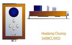
Stixx said:will look something like this...
Sexy

Looking forward to the pics
EDIT: for lower impedance headphones the same schematic with nfb might be better...psu is still the same.
White-CF are one of my favorite topologies for an ECC88 and family. You may find the compromise of NFB+low-Z phones not worth it. Just my

more bite....
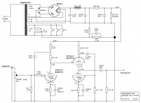
What about this one??
http://www.tubecad.com/2006/04/blog0062.htm
Built with 6CG7 and 6H30 it should have plenty of drive.
Build any psu you like to go with it...
(PCB's are resting in my drawer...)
What about this one??
http://www.tubecad.com/2006/04/blog0062.htm
Built with 6CG7 and 6H30 it should have plenty of drive.
Build any psu you like to go with it...
(PCB's are resting in my drawer...)
Broskie says that the amplifier has very good PSRR, but still a decent psu should be used...
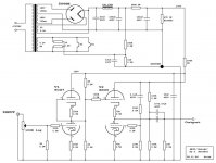
My implication also will have a tube rectified psu, probably dual mono, but for the low impedance variant something like this could do...
I assumed a total current draw of 88mA, using a 5U4 as rectifier. Anything smaller will of course also work but I like the look of those big rectifier tubes...
rgds,
Oliver
Attachments
Ok, Im getting a better grasp on this.
So in the PS I will need two 5u4g rectifier tubes, and a transformer, From what I read Im going to have to deal with heaters outside of the main circut, so what do i do to deal with that?
Also I understand that I will need to slightly modify the PCB so that i can run it to produce high current. Is there a thread that shows that alittle more or am I going to have to get it all from the link already provided.
I plan to start this pretty soon, though I could see it taking a month or so to get it all done and then more to case it.
-greg
*Edit*
I think that part of my slight problem is im not completely sure how to read every part of the schematic, mainly where the tubes and transformer come into play.
Im reading a tutorial on that right now.
Something that all of these designs seem to have in common is the use of a large electrolytic cap with 100V or more sitting on one side and a pair of headphones sitting on someone's head on the other.
I designed and built a white CF driven by an direct coupled SRPP based on this approach and haven't had a problem.. (So far) Still I can't recommend this for safety reasons and broach that concern here.
Under some circumstances this could be a potentially hazardous approach to one's hearing and a possible shock hazard as well if something were to go wrong. Should that cap fail abruptly the pop in one's exploding headphone driver could be deafening, and should the headphone cup not be adequately insulated it could be a shocking experience as well..
 (A small autoformer on the output would remove this concern and provide some impedance matching as well.)
Not to make light of all of this, but a small, super high quality output transformer from the likes of Hashimoto (etc) would be a lot safer.. Something along the lines of a 71A driving a 5/7K transformer would make a very nice and much safer headphone amplifier.
I designed and built a white CF driven by an direct coupled SRPP based on this approach and haven't had a problem.. (So far) Still I can't recommend this for safety reasons and broach that concern here.
Under some circumstances this could be a potentially hazardous approach to one's hearing and a possible shock hazard as well if something were to go wrong. Should that cap fail abruptly the pop in one's exploding headphone driver could be deafening, and should the headphone cup not be adequately insulated it could be a shocking experience as well..
(A small autoformer on the output would remove this concern and provide some impedance matching as well.)Not to make light of all of this, but a small, super high quality output transformer from the likes of Hashimoto (etc) would be a lot safer.. Something along the lines of a 71A driving a 5/7K transformer would make a very nice and much safer headphone amplifier.
Iv though of using out put transformers before, and like the idea. Expcially since I could match the 50 ohms of my headphones so well.
How much would I have to expect to spend to get a decent set of output transformers tho?
-greg
Also, isnt the risk of a cap failing in such a manner incredibly low? and couldent this be fixed with some output fuses?
How much would I have to expect to spend to get a decent set of output transformers tho?
-greg
Also, isnt the risk of a cap failing in such a manner incredibly low? and couldent this be fixed with some output fuses?
So in the PS I will need two 5u4g rectifier tubes, and a transformer, From what I read Im going to have to deal with heaters outside of the main circut, so what do i do to deal with that?
No, you will need one psu shown and split up after the last C...
For clarification I've attached the schematic of an aikido how I was planning to build it...It is the high impedance version since I am using Senn's, but it gives you an idea how to build a psu.
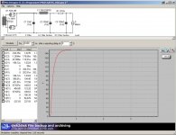
Reading a lot for sure helps, and getting PSUD2 to fiddle with parts values, different layouts and so on...
Also I understand that I will need to slightly modify the PCB so that
You don't have to modify the PCB...get the noval PCB from Broskie and stuff the parts according to YOUR schematic.
Under some circumstances this could be a potentially hazardous approach to one's hearing and a possible shock hazard as well if something were to go wrong. Should that cap fail abruptly the pop in one's exploding headphone driver could be deafening, and should the headphone cup not be adequately insulated it could be a shocking experience as well.. (A small autoformer on the output would remove this concern and provide some impedance matching as well.)
Kevin, I understand your worries...but I don't necessarily agree as long as the output caps are quality ones...
I am using Siemens mkv in my C3G headphone amp, and those are virtually indestructable and do sound much better than cheapo electrolytics!! They are quite large though...
Oliver
Attachments
Phergus_25 said:Iv though of using out put transformers before, and like the idea. Expcially since I could match the 50 ohms of my headphones so well.
How much would I have to expect to spend to get a decent set of output transformers tho?
I got a pair of electra-prints custom wound for about $200. You can also try Hammond 119DA's in this application. You would need to design around them, but they are only about $20 per. Another option is to parafeed and pick up a pair of Speco T-7010's. These are about $4 per. I am working on a board for this, but I won't be done with it for a few months, but the plan is an all tube parafeed headphone amp that can be built for under $120 or so. Seemed like a hole in the "available" projects.
Also, isnt the risk of a cap failing in such a manner incredibly low? and couldent this be fixed with some output fuses?
Yes, but in the cost benefit analysis, you need to consider the other side too. That is, while the probability is low, do you want to trust your hearing, and perhaps your life, to a cheap capacitor? Sometimes they are not made right, sometimes they see too high of a voltage, or too much heat, and sometimes they just get old. All sorts of things can go wrong.
Transformer coupled amps sound better anyway. OTL if is for chumps
Didn't Bas do a transformer coupled Aikido for headphones? I seem to remember something about that. Maybe a forum search will turn something up.
-d
Stixx said:I am using Siemens mkv in my C3G headphone amp, and those are virtually indestructable and do sound much better than cheapo electrolytics!! They are quite large though...
But he is using 50ohm phones, which means 6 or so of these in parallel per side to get a decent corner frequency.
Thanks for the new onslaught of info. I was hoping that you, dsavitsk, would jump in here.
I would be cool with trying out a transformer coupled amp, even if I had to do it with P2P, that is if I can at some point get a grasp on the design aspect of things.
When looking at the 119DA I am seeing 600 ohms, 4 and 8. Im sure its a simple matter, but ow would i impedence match that to 50? Or am I mis understanding this situation?
thanks
-greg
- Status
- This old topic is closed. If you want to reopen this topic, contact a moderator using the "Report Post" button.
- Home
- Amplifiers
- Headphone Systems
- Headphone amp with tube PS