kubeek said:Wavebourn, are referring to the schema posted by lineup? Could you post your altered version?
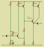
Here you go:

Let it be V1: BC550BP
V2,V3: BC237
V4,V6: BC135
V5: IRF610
For the same voltage gain R5=680, R6=220
But since the generic output follower is loaded by a current source, for maximum output voltage swing we should apply 8V to the gate, it means 4V on output.
It means emitter of V1 will see approximately 2V, base will see approximately 2.5V
For standard 47K input impedance let R1,R2 will be 100K each, R3=160K.
R4=5.1K
If to assume that idle current is 200 mA, beta of V9 is 100, R7=3.9K
R8 is preventing oscillations of the FET, let it be 1 KOhm, R9 let's take also 1K, R10=200 Ohm.
Maximal output swing will be about 4V if powered from 12V source, it is enough for forte-fortissimo with almost any headphones.
hey Wavebourn
I think I know what you were after in my headphones amplifier topic.
The attachment here, I posted already in December 2005
right after joining diyaudio as lineup.
I guess you mean like the first voltage stage in my schematic below.
Yes, this is one of my favourite voltage gain stages, all categories!
Simple - fast and very good!
This stage is often found in older discrete video amplifiers applications ......
I might put together and make some comparing simulation tests
using this topology for a second headphone amplifier.
I am not sure this 'your suggestion' would be the loser")
-----------------------------------------------
The first time I posted this Eagle schematic was in
diyAudio Forums > Top >Amplifiers >Solid State >simplest amplifier possible with BJT's
See this post #90
http://www.diyaudio.com/forums/showthread.php?postid=797165#post797165
regards
lineup
I think I know what you were after in my headphones amplifier topic.
The attachment here, I posted already in December 2005
right after joining diyaudio as lineup.
I guess you mean like the first voltage stage in my schematic below.
Yes, this is one of my favourite voltage gain stages, all categories!
Simple - fast and very good!
This stage is often found in older discrete video amplifiers applications ......
I might put together and make some comparing simulation tests
using this topology for a second headphone amplifier.
I am not sure this 'your suggestion' would be the loser
-----------------------------------------------
The first time I posted this Eagle schematic was in
diyAudio Forums > Top >Amplifiers >Solid State >simplest amplifier possible with BJT's
See this post #90
http://www.diyaudio.com/forums/showthread.php?postid=797165#post797165
regards
lineup
Attachments
Lineup, this stage reflects K.I.S.S. principle that may be properly applied to audio design as well. When people run for symmetrical distortions they run against Mother - Nature that generates symmetrical distortions only when mechanical oscillating systems are abused. Also, designs that show higher THD on lower powers are again go against Mother Nature: the louder is the sound in reality, the reacher it is with harmonics.
People who run for symmetrical distorting amplifiers that distort symmetrically and the more distort the less is loudness, hawe to feed the sound to some Matrix robot, instead of to real human ears and bodies.
People who run for symmetrical distorting amplifiers that distort symmetrically and the more distort the less is loudness, hawe to feed the sound to some Matrix robot, instead of to real human ears and bodies.
Wavebourn said:Let it be V1: BC550BP
V2,V3: BC237
V4,V6: BC135
V5: IRF610
Too bad the transistors are not marked in your schematic, but fortunately we can make educated guesses
. BTW shouldn't V4, V6 be BD135 (not BC135)?ilimzn said:
Too bad the transistors are not marked in your schematic, but fortunately we can make educated guesses
Oops...
 Sure, BD135 - the same as in lineup's version!
Probably, a current mirror instead of R9 containing a diode and resistor in series will improve current source's linearity, but anyway it has much higher dynamic resistance than resistors in Lineup's design, so let's leave it as is and try this way.
No success, I yesterday tried to simulate your circuit, and I wasn´t able to get it working, I couldn´t achieve the output stage to have some reasonable current through it, the mosfet doesn´t open enough.
I am not sure if I didn´t make any mistakes when redraving the picture, the output stage is quite complicated.
BTW you forgot to nuber the transistors, so I can´t tell vhere the stated voltages should be. Also the mosfet is a little bit ambigious, but as it is IRF610, it should be N-type with source pointing down, right?
kubeek said:No success, I yesterday tried to simulate your circuit, and I wasn´t able to get it working, I couldn´t achieve the output stage to have some reasonable current through it, the mosfet doesn´t open enough.
I am not sure if I didn´t make any mistakes when redraving the picture, the output stage is quite complicated.
The output stage is actually very simple, though uncommon:
At top: FET and BJT followers in parallel. When "MOSFET does not open enough" BJT emitter follower does the job.
At bottom: current source, current depends on input voltage, R7 and beta of right bottom BJT transistor.
What load did you try it on?
Idle current depends on R7. 3.9K on 4v gives approximately 1 mA.
If beta of current amplifier (bottom right transistor) is 100, idle current will be 100 mA. Maximum peak current will be (8V/3.9K)*100 = 200 mA. It means, 6/0.2=12 Ohm minimal load impedance. Good enough for 32 Ohm headphones.
However, if you are going to drive speaker, or lower impedance headphones, or beta of transistor is much smaller than 100, you will need to adjust R7 value.
kubeek said:I have 0.125V on the output. The amp looks like this:
Swap R5 and R6.
kubeek said:I swapped them, also lowered R2 to 90k to get output to 8V, but the output is assymetricaly distorted (not limited), lower part looks like sine, but the upper is too flat.
What load resistance do you use?
It can't give voltage on infinite load rail to rail, it is designed to give 4V P-P on 32 Ohm headphones, voltage on output must be 4V.
Just connect 32 Ohm load and tune R2 until you get maximum available undistorted output.
At the top it is limited by driver (V1, V2) and VGS of V5, at the bottom - by current source (V4,V6).
Wavebourn said:
What load resistance do you use?
It can't give voltage on infinite load rail to rail, it is designed to give 4V P-P on 32 Ohm headphones, voltage on output must be 4V.
Just connect 32 Ohm load and tune R2 until you get maximum available undistorted output. 12V p-p would damage headphones, or ears.
At the top it is limited by driver (V1, V2) and VGS of V5, at the bottom - by current source (V4,V6).
I am not aiming 12Vpp of course and know it is not possible with this design. I measured with 100mV input and no load, as well as with 220ohm + 1000uF in series.
So the idle voltage on output should be 4V?
Changed R2 to get 4V.
The sine was perfect till the gate, and also on R7, but on R9 it was assymetrical.
I set R9 to 6K, now the distortion is only 0.012%@1kHz, 10mV input. The only component is 2nd harmonic. With R9 1k it was 0.27%, again 2nd harmonic.
So the idle voltage on output should be 4V?
Changed R2 to get 4V.
The sine was perfect till the gate, and also on R7, but on R9 it was assymetrical.
I set R9 to 6K, now the distortion is only 0.012%@1kHz, 10mV input. The only component is 2nd harmonic. With R9 1k it was 0.27%, again 2nd harmonic.
kubeek said:I am not aiming 12Vpp of course and know it is not possible with this design. I measured with 100mV input and no load, as well as with 220ohm + 1000uF in series.
So the idle voltage on output should be 4V?
Yes!
Changed R2 to get 4V.
The sine was perfect till the gate, and also on R7, but on R9 it was assymetrical.
I set R9 to 6K, now the distortion is only 0.012%@1kHz, 10mV input. The only component is 2nd harmonic. With R9 1k it was 0.27%, again 2nd harmonic.
Sure, it is most naturally sounding output stage I've ever designed.
R9 adds distortions, but it is needed to dump unwanted currents and discharge capacitances. Try 510 Ohm in series with diode, also check on 20 KHz with 32 Ohm load.
kubeek said:Just by the way, the lineup´s original has about the same 2nd harmonic, but more higher harmonics, in the order of 0.0025-0.001.
Your design has 3rd and higher harmonics 0.00004 and lower
Reality is, no tubes needed if to use transistors properly.
Also, if P-type vacuum tubes were invented earlier than transistors we would not call that harsh sound "Transistor sound". Transistors are inocent, desighers are guilty.

kubeek said:I tried the diode and 510 ohm, it resulted in 0.017% with no other harmonics.
I like that, guess I will build this one instead of the lineup´s, hope I won´t have to troubleshoot it like I did in the simulation.
Are BC550/560 suitable for the input stage?
Yes!
In reality you may use 20K trimpot for R7, since beta of real BD135 vary. Also, you may put series of them on a switch, for different output loads.
- Status
- This old topic is closed. If you want to reopen this topic, contact a moderator using the "Report Post" button.
- Home
- Amplifiers
- Headphone Systems
- Best sounding headphone amp from Wavebourn to Kubeek :)