.
Hello lovers of diyAudio
My Headhone Amp project
for you?
Schematic and detailed description is a part of
Destroyer X very good topic:
http://www.diyaudio.com/forums/showthread.php?postid=997007#post997007
Enjoy da Musica!
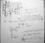
Here is my lineup original idea,
with Component layout of my circuit
( please respect my full copy right to this amplifier )
Hello lovers of diyAudio
My Headhone Amp project
for you?
Schematic and detailed description is a part of
Destroyer X very good topic:
http://www.diyaudio.com/forums/showthread.php?postid=997007#post997007
Enjoy da Musica!
Here is my lineup original idea,
with Component layout of my circuit
( please respect my full copy right to this amplifier )
Attachments
Despite Line up....this circuit is very interesting..i am very interested.
My resistance to construct it immediattely is because the power consumption.....as i will have to produce a supply, and this means that will not be portable anymore...attached to the mains...hummm...not good to MP3 player...as will need to be fixed.!
I am thinking to reduce voltage and current, to recalculate the whole thing to lower voltage transistors, and to use Nickel Cadmiun batteries, and i have a lot of them..all brand new..costed 1 dollar each one...950 miliamps each unit..AA sized.
The circuit may sound very good, as it is simple and class A...and with differential that we can try to make better that feedback line.
Yes...batteries may be noisy...but we can try to filter that noise.
regards,
Carlos
Dear DorinD,
i am sorry but i did not build this little thing...it is entirely made by Lineup....he will be back in a couple of days and i am sure that he will answer Your question....
I assume that You don't have to worry because he made it and he reported that the sound is simply wonderfull.....
best regards
daniel
my dear Carlos....i am happy that you are interested in this amp....yes i agree with you that the consumpiton is a little bit to much for the batteries...but i have a small transformer in my home that has (i think) the proper voltage needed for the amp and the transformer is not to big....i think this still can be preety small for class A...small enough to be used with my laptop....")

i am looking forward on what you will do...(smaller fo the batteries) - but i am courious if this will destroy some of the magic - maybe it will.....
regards
i am sorry but i did not build this little thing...it is entirely made by Lineup....he will be back in a couple of days and i am sure that he will answer Your question....
I assume that You don't have to worry because he made it and he reported that the sound is simply wonderfull.....
best regards
daniel
my dear Carlos....i am happy that you are interested in this amp....yes i agree with you that the consumpiton is a little bit to much for the batteries...but i have a small transformer in my home that has (i think) the proper voltage needed for the amp and the transformer is not to big....i think this still can be preety small for class A...small enough to be used with my laptop....
i am looking forward on what you will do...(smaller fo the batteries) - but i am courious if this will destroy some of the magic - maybe it will.....
regards
some more information
o.k. guys....
i have received a very nice mail from the guy that started this thread (thanks lineup for the kind words).....
i will quote him - it is the best.....
======================================
about my amplifier:
you see the load is 100 Ohm.
In fact the omtimal load for this type of class A is
resistors = headphone impedance
this will give maximum output power
and this means, setup is also the best QUALITY low distortion
performance
when load is = resistance in output stage
My output stage, is in fact compromise,
for amplifier to be good form 32 - 300 Ohm headphones
100 Ohm is in middle*!
formula:
if LOW = 32 and HIGH = 300 Ohm phones, you want to use
square root( LOW x HIGH ) = 97.79 Ohm
so, if you want to make special version for 32 Ohm
and lower voltage, it can be done
no problem
only some matematicals and some thinking
and some little changes
*************
lineup
====================================
best regards and happy diy
thanks sparkle
sparkle
thanks for your schematic clean-up
http://www.diyaudio.com/forums/attachment.php?s=&postid=999712&stamp=1157628903
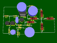
Just for fun
here is how an electronics program wants to arrange PCB layout.
I wouldnt build it like that.
I have shown a drawing in a previous post here,
my idea of a perfect placing of components onto a board.
Anyway
here is the computed suggestion
from a good but a bit stupid electronics program.
You know such programs, just like some people,
have very low ability to think out of the box
Newbies and audio beginners, still have plenty of this quality.
As they are not yet inside the square and improved box of accepted audio ideas.
This is one reason, I like so much to exchange ideas with new diyAudio members.
Good for my creativity
lineup
sparkle
thanks for your schematic clean-up
http://www.diyaudio.com/forums/attachment.php?s=&postid=999712&stamp=1157628903
Just for fun
here is how an electronics program wants to arrange PCB layout.
I wouldnt build it like that.
I have shown a drawing in a previous post here,
my idea of a perfect placing of components onto a board.
Anyway
here is the computed suggestion
from a good but a bit stupid electronics program.
You know such programs, just like some people,
have very low ability to think out of the box
Newbies and audio beginners, still have plenty of this quality.
As they are not yet inside the square and improved box of accepted audio ideas.
This is one reason, I like so much to exchange ideas with new diyAudio members.
Good for my creativity
lineup
Attachments
Your ideas are rigth and i apreciate them very much
Good analisis and evaluation of some people behavior...... they are exceptions....not a rule.
Your posts are different....better in my point of view, as they show that there's a human being in the other side....not a computer terminal writing things...a real man in the other side.
One added to one will be not always two..... if those ones constitute a couple.... married persons...this can result in three, four, five or more...including the kids....in electronics can be applied to many things...including harmonics.
A little bit more flexibility using the brain, is more than adequated.
Sparkle is sick...he is facing a storm in his life, i am not sure if he will be able to answer you Lineup
regards,
Carlos
Re: Your ideas are rigth and i apreciate them very much
Very sorry to hear this, Carlos.

He was very understanding and helpful to me, when I started this topic
and was waiting in house-arrest for 10 days.
Planet10 was also a great comfort to me. Dave is alright.
Hope things will get better for Sparkle.
As far as I can tell, our friend does not deserve to be not happy and feeling bad.
regards
lineup
destroyer X said:
Sparkle is sick...he is facing a storm in his life, i am not sure if he will be able to answer you Lineup
regards,
Carlos
Very sorry to hear this, Carlos.
He was very understanding and helpful to me, when I started this topic
and was waiting in house-arrest for 10 days.
Planet10 was also a great comfort to me. Dave is alright.
Hope things will get better for Sparkle.
As far as I can tell, our friend does not deserve to be not happy and feeling bad.
regards
lineup
Hi Headphones amp guru here
this amp is truly good
is it supposed to be powered by mains supply?
there will be hum issues
also i feel o/p could have been more heavily biased
but it would make battery operation impracticable
for battery operation the circuit is very good
lineup has done a great job
cheers
john
this amp is truly good
is it supposed to be powered by mains supply?
there will be hum issues
also i feel o/p could have been more heavily biased
but it would make battery operation impracticable
for battery operation the circuit is very good
lineup has done a great job
cheers
john
johndiy said:Hi Headphones amp guru here
this amp is truly good
is it supposed to be powered by mains supply?
......
for battery operation the circuit is very good
lineup has done a great job
cheers
john
I hate it when mastergurus, cant do their basic research homework properly.
Power supply info is linked to in first posts of this thread.
More images and facts and details and presentation of my design is first posted
in destroyer X, my friend Carlos very nice headphone amp topic.
lineup
sometimes think his good friends do not know how to read
 maybe lineup will be so kind sit at their bedside
 reading for them, until go to sleep tight
check this out a heavily biased high powered headphones
amp class-a ofcourse and no nfb dynamics
http://members.dodo.com.au/g3000/
john
amp class-a ofcourse and no nfb dynamics
http://members.dodo.com.au/g3000/
john
Discrete Headphones ClassA amplifier - New version
Hello
thanks for your interest
this amplifier should be no problem to build
any contribution of PCB Layout Design .... fine thank you!
the original has got BOTH channels + one 12V regulator in one board
Designed to suit 90% of all commonly sold headphones.
Recommended Headphones Impedance: 32 - 300 ohm
Short general description:
100% Single Ended Class A operation.
One 3T discrete voltage amplifier, gain x4, with feedback,
with voltage output to a single NPN Voltage follower transistor ( buffer )
operating at 80 milliampere Class A current into resistive load.
...............................................................................
Data:
Input impedance: 22 kohm
Output impedance: 100 ohm
Voltage Gain: 4.0 ( +12dB )
Voltage supply: 12.0 VDC, Regulated
Current supply: 95 mA per channel
...............................................................................
Easy to find parts:
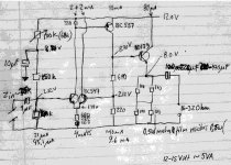
POWER SUPPLY:
- <100 mA per channel.
- Transformer 12VAC, 5-10 VA
- Rectifier bridge 1.0A or 4 Silicon Diodes 1.0A.
- 7812 regulator TO220, 12 Volt 0.5-1.0A
...............................................................................
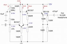
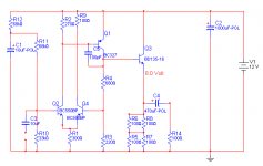
New version, See Attachment Schematic,
components, changes, comments:
Q2-Q4 : TO92 : BC550C, BC547 or most any small TO92
Q1 : TO92 : BC327, BC328, BC640. 2N5401 will also work perfectly.
Q5 : TO126 : BD135, BD139. Also MJE340 will be fine.
R9, 100 Ohm, was only for measurement in my Spice Simulation.
To get 50-50% Current in Q2-Q4.
Not needed. Should be removed after eventual measuring.
C5, 100pF, was added.
Makes sure amp is stable and lowers distortion.
C3, 10uF. INPUT.
Should be film capacitor MKP Polypropylene or MKT Polyester. Like 2.2uF will be good.
For better square wave looks in my testings, an overkill high value was used.
C4, 470uF. OUTPUT.
Depending of your HeadPhones impedance this can be 100uF - 1.000uF.
470uF will do well with most headphones, 32 - 300 Ohm impedance.
A Good Quality electrolytic capacitor is more important,
than the actual value within 100uF - 1.000uF.
All resistors are metal film 0.25Watt.
4 resistors 100 Ohm, 0.25W in parallel/series is used
to make up one 1.0W METAL FILM resistor in output stage. ( 4x0.25=1.0W )
Because metal film resistors are the best quality resistance we can get.
Better than wire wound power resistors!
...............................................................................................
The amplifier voltage gain is defined by (R4+R3)/R3
900/220....... ~4.0 ( +12dB )
Unless you know what you are doing, R4 and R3 should not be changed.
Because this would upset the whole circuit.
Enjoy!
lineup
Lineup Audio Lab
http://lineup.awardspace.com/
Hello
thanks for your interest
this amplifier should be no problem to build
any contribution of PCB Layout Design .... fine thank you!
the original has got BOTH channels + one 12V regulator in one board
Designed to suit 90% of all commonly sold headphones.
Recommended Headphones Impedance: 32 - 300 ohm
Short general description:
100% Single Ended Class A operation.
One 3T discrete voltage amplifier, gain x4, with feedback,
with voltage output to a single NPN Voltage follower transistor ( buffer )
operating at 80 milliampere Class A current into resistive load.
...............................................................................
Data:
Input impedance: 22 kohm
Output impedance: 100 ohm
Voltage Gain: 4.0 ( +12dB )
Voltage supply: 12.0 VDC, Regulated
Current supply: 95 mA per channel
...............................................................................
Easy to find parts:
POWER SUPPLY:
- <100 mA per channel.
- Transformer 12VAC, 5-10 VA
- Rectifier bridge 1.0A or 4 Silicon Diodes 1.0A.
- 7812 regulator TO220, 12 Volt 0.5-1.0A
...............................................................................
New version, See Attachment Schematic,
components, changes, comments:
Q2-Q4 : TO92 : BC550C, BC547 or most any small TO92
Q1 : TO92 : BC327, BC328, BC640. 2N5401 will also work perfectly.
Q5 : TO126 : BD135, BD139. Also MJE340 will be fine.
R9, 100 Ohm, was only for measurement in my Spice Simulation.
To get 50-50% Current in Q2-Q4.
Not needed. Should be removed after eventual measuring.
C5, 100pF, was added.
Makes sure amp is stable and lowers distortion.
C3, 10uF. INPUT.
Should be film capacitor MKP Polypropylene or MKT Polyester. Like 2.2uF will be good.
For better square wave looks in my testings, an overkill high value was used.
C4, 470uF. OUTPUT.
Depending of your HeadPhones impedance this can be 100uF - 1.000uF.
470uF will do well with most headphones, 32 - 300 Ohm impedance.
A Good Quality electrolytic capacitor is more important,
than the actual value within 100uF - 1.000uF.
All resistors are metal film 0.25Watt.
4 resistors 100 Ohm, 0.25W in parallel/series is used
to make up one 1.0W METAL FILM resistor in output stage. ( 4x0.25=1.0W )
Because metal film resistors are the best quality resistance we can get.
Better than wire wound power resistors!
...............................................................................................
The amplifier voltage gain is defined by (R4+R3)/R3
900/220....... ~4.0 ( +12dB )
Unless you know what you are doing, R4 and R3 should not be changed.
Because this would upset the whole circuit.
Enjoy!
lineup
Lineup Audio Lab
http://lineup.awardspace.com/
Attachments
Wavebourn said:Lineup,
remove right transistor from your differential input and your amp will sound better
Sorry, Wavebourn.
But we shouldn't possibly destroy a winning concept
and make something else out of it.
This amplifier was built with a fantastic sound in my headphones
and so thinks my friends that has listened to it ....
You do this in your version of my amplifier. With a different sound.
Nobody can stop you!
Or why not start a new topic:
'Lineup Audio Lab HeadAmp clone by Wavebourn'
Thanks for interest
Chief Burning Waveany thing to bring a good topic upfront is welcome
regards
lineup
- Status
- This old topic is closed. If you want to reopen this topic, contact a moderator using the "Report Post" button.
- Home
- Amplifiers
- Headphone Systems
- Discrete Single End TRUE Class A HeadPhone Amplifier