kubeek said:
Then I changed r5-r8 to total 50ohms, to drive 16ohm headphones too, is it allright with 50ohm?
About changing those resistors R10, R11, R12 in input:
I think the New Version input will work better. Without changes.
see schematic:
http://www.diyaudio.com/forums/attachment.php?s=&postid=1056862&stamp=1163538498
-----------------------
Those R5-6-7-R8 in output are not very critical to change.
They wont effect the rest of circuit very much at all.
As long as output resistors and transistor can take the heat (may need a small heatsink)
and the power supply can deliver the current to this output transistor.
You did the absolute correct thing, in your special case,
when changing to 47 Ohm.
Because my design is targeted for lowest 32 ohm phones.
16 is half, and you did half the output impedance.
This doubles the output current, from 80 mA to ~160 mA.
Some 8 or 16 Ohms phones may need a bit more current = lower output resistance.
If for example using this amp with 300 / 600 ohm phones,
it may be an idea try to use higher value, maybe 150-220 ohm for these resistors.
Theoretically these resistors (resistive loading)
should be equal to headphones impedance for an optimum result.
I have used a compromise, between 32-300 ohm.
Because I had several different headphones at home and in mind for my design.
100 ohm and gain x4 will best fit most headphones in a good way.
Would normally work very well with 16 ohm and 600 ohm headphones, too.
Headphones at 8 ohm, I would not recommend using, though.
Not with the standard schematic circuit values.
lineup
lineup said:
Sorry, Wavebourn.
But we shouldn't possibly destroy a winning concept
and make something else out of it.
This amplifier was built with a fantastic sound in my headphones
and so thinks my friends that has listened to it ....
You do this in your version of my amplifier. With a different sound.
Nobody can stop you!
Or why not start a new topic:
'Lineup Audio Lab HeadAmp clone by Wavebourn'
Thanks for interest
any thing to bring a good topic upfront is welcome
regards
lineup
Ok, done: http://www.diyaudio.com/forums/showthread.php?s=&threadid=90324
SPICE it and compare. You may breadboard it as well to check correlation between SPICE models and sonic qualities.

Re: Despite Lineup....this circuit is very interesting..i am very interested
You were interested and helpful, Sparkle
in my creation of this topic of 'my best ever amplifier'.
Sparkle,
I wonder if you built one? Sound?
Carlos M.
you said in 'your' headphone topic,
that you had designed 3 V and 9 Volt version of my amplifier.
You promised you should 'post results' later
Did sound good or bad?
... maybe my circuit was too good in compare to your own nice headphone amp project
... who wants to be left in the shadow when other in sunshine
Regards
lineup - Lineup Audio Labs - http://lineup.awardspace.com/
cheers
---------------------
PS.
Attached Schematic Link shows:
Latest Published version ( I have 2-3 further improved & refined version )
Copyright: Lineup Audio Labs
License: diyAudio Member is Free to build 1 copy for Personal use
Schematic: http://www.diyaudio.com/forums/attachment.php?s=&postid=1056862&stamp=1163538498
destroyer X said:Despite Lineup....this circuit is very interesting..i am very interested
My resistance to construct it immediattely is because the power consumption.....as i will have to produce a supply, and this means that will not be portable anymore...attached to the mains...hummm...not good to MP3 player...as will need to be fixed.!
------------
Carlos
destroyer X said:Lineup,
Good analisis and evaluation of some people behavior...... they are exceptions....not a rule.
Your posts are different
....better in my point of view,
as they show that there's a human being in the other side.
...not a computer terminal writing things
...a real man in the other side.
---------------
Carlos
lineup said:
Sparkle has got difficult situation.
Very sorry to hear this, Carlos.
He was very understanding and helpful to me, when I started this topic
and was waiting in house-arrest for 10 days.
Planet10 was also a great comfort to me. Dave is alright.
Hope things will get better for Sparkle.
As far as I can tell,
our friend does not deserve
to be not happy and feeling bad.
regards
lineup
You were interested and helpful, Sparkle
in my creation of this topic of 'my best ever amplifier'.
Sparkle,
I wonder if you built one? Sound?
Carlos M.
you said in 'your' headphone topic,
that you had designed 3 V and 9 Volt version of my amplifier.
You promised you should 'post results' later
Did sound good or bad?
... maybe my circuit was too good in compare to your own nice headphone amp project
... who wants to be left in the shadow
when other in sunshineRegards
lineup - Lineup Audio Labs - http://lineup.awardspace.com/
cheers
---------------------
PS.
Attached Schematic Link shows:
Latest Published version ( I have 2-3 further improved & refined version )
Copyright: Lineup Audio Labs
License: diyAudio Member is Free to build 1 copy for Personal use
Schematic: http://www.diyaudio.com/forums/attachment.php?s=&postid=1056862&stamp=1163538498
Sorry lineup, i have not constructed your headphone amplifier.
I gave up related that construction...things happened i my life, the North changed to Northeast and i start to produce my own amplifier.
I am constructing mine, developing mine unit for a while.
regards,
Carlos
I gave up related that construction...things happened i my life, the North changed to Northeast and i start to produce my own amplifier.
I am constructing mine, developing mine unit for a while.
regards,
Carlos
PCB Layout of Class A headphone amplifier
Nordic
Your layout will probably work, at a qucik look,
if there is no RAILS bug,error, when you test in LTspice/Eagle.
You use un-regulated, with Big supply caps. ( ...hope is not Black! )
My recommendation is LM317 Regulated, exactly 12 Volt.
Because my circuit was designed for .... 12.000V.
And will work & sound the best when setup as intended
Further, some notes:
1. I would use my upgraded version. Latest schematic posted.
2. Use one or two LM317(one per channel) for supply regulation.
3. I would consider a layout more like shown in my fist post her
= my layout
.. that can really sing and is proven very good.
In this image you can see how I organized the small PCB (compare to MatchBox size)
To the left you have one LM317, connected in between left/right.
The light blue CAP to the right is supply bypass cap for output transistors.
http://www.diyaudio.com/forums/attachment.php?s=&postid=995733&stamp=1157137237
For this sort of simple ( 4 T, only four transistors )
we should try to be very careful with what Power Supply we use.
It will NOT have such high magic numbers in PSRR, Power Supply Rejection Ratio
as for example a G. Kleinschmidt '50 Transistors' design.
This does mean the sound of a 4T Class A may be inferior.
Quite the opposite sometimes.
Which is my own experience with this little Goddie amp
==================================================
For reading my instructions and understand more of this amplifier & its power supply:
1. first introduction post, by lineup
http://www.diyaudio.com/forums/showthread.php?postid=995718#post995718
2. IMAGE: my homemade stereo board is 47.5 x 62.5 mm
http://www.diyaudio.com/forums/showthread.php?postid=995720#post995720
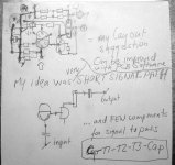
3. IMAGE. circuit is extremely compact (about 20x20 mm for each amp)
short signal travel was my obsession those days long ago[
http://www.diyaudio.com/forums/showthread.php?postid=995722#post995722
4. IMAGE ATTACHMENT. My first posted schematic of MK1 = my original version.
The version I still use for my HeadPhone listenings!
http://www.diyaudio.com/forums/showthread.php?postid=996721#post996721
 ... ... ...
... The easy & prefered way to learn as much as possible, before build, is:
1. START here and read all MY posts in topic/thread of my brasil friend:
http://www.diyaudio.com/forums/showthread.php?postid=995718#post995718
2. Then GO HERE
http://www.diyaudio.com/forums/showthread.php?s=&threadid=86020
.... and read all further details.
I started this separate thread to not disturb my friend from brasil.
He showed me clearly, even if not in words, he would want it this way
And I accepted this fact, in the end. = got meself my own topic
____________
Experts Analysts and Academics tend to stick to Mainstream Paradigms
else if they go against they may be
considered dissidents who threaten to make obsolete
knowledge to which the majority of experts
have committed themselves
Nordic said:Ok here is a fixed version...
Nordic
Your layout will probably work, at a qucik look,
if there is no RAILS bug,error, when you test in LTspice/Eagle.
You use un-regulated, with Big supply caps. ( ...hope is not Black! )
My recommendation is LM317 Regulated, exactly 12 Volt.Because my circuit was designed for .... 12.000V.
And will work & sound the best when setup as intended
Further, some notes:
1. I would use my upgraded version. Latest schematic posted.
2. Use one or two LM317(one per channel) for supply regulation.
3. I would consider a layout more like shown in my fist post her
= my layout
.. that can really sing
and is proven very good.In this image you can see how I organized the small PCB (compare to MatchBox size)
To the left you have one LM317, connected in between left/right.
The light blue CAP to the right is supply bypass cap for output transistors.
http://www.diyaudio.com/forums/attachment.php?s=&postid=995733&stamp=1157137237
For this sort of simple ( 4 T, only four transistors )
we should try to be very careful with what Power Supply we use.
It will NOT have such high magic numbers in PSRR, Power Supply Rejection Ratio
as for example a G. Kleinschmidt '50 Transistors' design.
This does mean the sound of a 4T Class A may be inferior.
Quite the opposite sometimes.
Which is my own experience with this little Goddie amp
==================================================
For reading my instructions and understand more of this amplifier & its power supply:
1. first introduction post, by lineup
http://www.diyaudio.com/forums/showthread.php?postid=995718#post995718
2. IMAGE: my homemade stereo board is 47.5 x 62.5 mm
http://www.diyaudio.com/forums/showthread.php?postid=995720#post995720
3. IMAGE. circuit is extremely compact (about 20x20 mm for each amp)
short signal travel was my obsession those days long ago[
http://www.diyaudio.com/forums/showthread.php?postid=995722#post995722
4. IMAGE ATTACHMENT. My first posted schematic of MK1 = my original version.
The version I still use for my HeadPhone listenings!
http://www.diyaudio.com/forums/showthread.php?postid=996721#post996721
... ... ... ... The easy & prefered way to learn as much as possible, before build, is:
1. START here and read all MY posts in topic/thread of my brasil friend:
http://www.diyaudio.com/forums/showthread.php?postid=995718#post995718
2. Then GO HERE
http://www.diyaudio.com/forums/showthread.php?s=&threadid=86020
.... and read all further details.
I started this separate thread to not disturb my friend from brasil.
He showed me clearly, even if not in words, he would want it this way
And I accepted this fact, in the end. = got meself my own topic
____________
Experts Analysts and Academics tend to stick to Mainstream Paradigms
else if they go against they may be
considered dissidents who threaten to make obsolete
knowledge to which the majority of experts
have committed themselves
Attachments
Lineup, i have an urgent message to you
I have already posted this 4 times.
You are ignoring the message, your mistake,it is very important!
I need an adress to send you an audio message.
The message size is 3.5 Megabytes.
I ensure that this message is important, not only to me, but important to YOU.
This is the last time i ask you the E mail adress, as i have used forum to personal messages.... forum not made for that.
We need to inform contact mail adress...you are not giving this chance to us.... this keep your position as "one way street"...as you talk with us and we cannot talk with you.
The E mail adress i am asking you, is a different one, related the other ones you provide that return the message back to the sender.
Carlos
kubeek said:I personaly changed R10 to 47K, because it won´t work with 120k at all.
Then I changed r5-r8 to total 50ohms,
to drive 16ohm headphones too, is it allright with 50ohm?
It will work alright with 47 kohm, too.
Using 50 Ohms output load, is no problem.
And for 16 Ohms headphones this can even give better, more current pushing
For 32 Ohms HP:s (and higher impedances)I would not change the original value for R5,6,7,8
It is carefully tuned to give very good result using these values
at 12 VDC operation
And HeadPhones 32 Ohm or higher.
regars
lineup
- Status
- This old topic is closed. If you want to reopen this topic, contact a moderator using the "Report Post" button.
- Home
- Amplifiers
- Headphone Systems
- Discrete Single End TRUE Class A HeadPhone Amplifier