This is a continuation of the idea that originally formed in this thread: http://www.diyaudio.com/forums/showthread.php?postid=945463#post945463
After a little thought, the design could be quite simple. The high side would have a pnp connected to the rail and the inductor, its base connected to the collector of an npn through a resistor. The emitter of the npn would be grounded, and the comparator would drive the base through a resistor. Mirror that for low side (using npn's instead of pnp's and pnp's instead of npn's) and it should be very simple to build. The output stage parts would include 2 pnp's, 2 npn's, and 4 resistors. The comparator would be an IC, and the feedback loop/input parts would include 3 resistors and a capacitor. That could be a bare bones implementation. I'll try to draw up a schematic and maybe come up with some part values a little later tonight.
Everyone feel free to list what they'd like to see from a class d headphone amp!
This is an interesting project, should be fun to see and hear what comes of it.
Let me play Devil's advocate here, to give the design team some things to think about.
1) Input buffer. Most Class-D amps use an input buffer before the modulator. And what is that buffer? An op-amp! You can make a darn good, easy and cheap headphone amp with the right op-amp. Is the Class-D power stage going to sound better than the op-amp buffer? Think about that. (The buffer does not need to be an opamp, BTW).
2) RFI. Looks like we will go with a non-bridged design? That means the potential of a full power radio frequency square wave applied to the phones. You'll need to get that filter just right. Probably a 2nd order filter, at least. Post filter feedback?
3) Noise. Switching amps are noisy. But the noise is far enough down that it is not, or almost not, audible on regular speakers. Headphones are much more sensitive. Noise is likely to be a big problem.
The only practical benefits of a class-D headphone amp are efficiency and portability, so a 5v volt max swing might be acceptable.
If it is, why bother with a discrete output, a few paralleled CMOS gates will give you an output stage with plenty of current capability, FAST transition times, and a high impedance, couple hundred pF, input impedance.
If it is, why bother with a discrete output, a few paralleled CMOS gates will give you an output stage with plenty of current capability, FAST transition times, and a high impedance, couple hundred pF, input impedance.
You can make a great headphone amp with an op-amp... BUT a class d headphone amp could be scaled to give you more power output. Plus, a class d power stage might sound better than an op-amp bufferpanomaniac said:Most Class-D amps use an input buffer before the modulator. And what is that buffer? An op-amp! You can make a darn good, easy and cheap headphone amp with the right op-amp. Is the Class-D power stage going to sound better than the op-amp buffer? Think about that. (The buffer does not need to be an opamp, BTW).

Standard UCD second order filter to start, maybe a 4th order with feedback after both filters if the concept is feasible...panomaniac said:2) RFI. Looks like we will go with a non-bridged design? That means the potential of a full power radio frequency square wave applied to the phones. You'll need to get that filter just right. Probably a 2nd order filter, at least. Post filter feedback?
If we can get the switching frequency high enough and keep the output filter cutoff down low then we can hopefully get rid of a lot of noise. A 4th order filter would help even further in that respect.panomaniac said:3) Noise. Switching amps are noisy. But the noise is far enough down that it is not, or almost not, audible on regular speakers. Headphones are much more sensitive. Noise is likely to be a big problem.
Are those the only benefits? I didn't replace my 50W per channel receiver with an 8W per channel class d amp because it was more efficient or portable! The whole idea is good sound, although efficiency and small size are pleasant "side effects".Tim__x said:The only practical benefits of a class-D headphone amp are efficiency and portability, so a 5v volt max swing might be acceptable.
+/-5V rails with a single ended amp will allow a maximum of 5.9mWrms output power into 600ohms, and that's assuming you have full rail-to-rail swing. That figure increases to 110mWrms for a 32ohm load. Not much power for high impedance cans, but it could probably work well for lower impedance cans.
Why bother with CMOS chips when you can get transistors for cents a piece? Transistors can have higher voltage and current ratings as well. That would make the design more scalable.Tim__x said:If it is, why bother with a discrete output, a few paralleled CMOS gates will give you an output stage with plenty of current capability, FAST transition times, and a high impedance, couple hundred pF, input impedance.
You don't need an op amp buffer at all, just drive the comparator directly.
You dont' need a 4'th order filter, just more junk to pollute the signal path. Keep it simple, keep it pure, keep it clean.. it'll pay off. That's alot of the magic behind the UCD in the first place, remember?
You dont' need a 4'th order filter, just more junk to pollute the signal path. Keep it simple, keep it pure, keep it clean.. it'll pay off. That's alot of the magic behind the UCD in the first place, remember?
classd4sure said:You don't need an op amp buffer at all, just drive the comparator directly.
You dont' need a 4'th order filter, just more junk to pollute the signal path. Keep it simple, keep it pure, keep it clean.. it'll pay off. That's alot of the magic behind the UCD in the first place, remember?
Like coupling caps, a buffer is something that we'd like to do without!
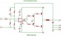
We may not need a 4th order filter, but if it were inside the feedback loop then it wouldn't pollute the signal path. I'll draw up my idea for the 4th order filter w/feedback and post it here to see what you guys think. For now, here's a schematic of what I had in mind. If anyone has suggestions for improvement, or suitable devices, please say so. I used the LT1016 part for the comparator because it readily available in eagle and would probably work ok with this design. Any other comparator could be used, and with the way the output stage is set up, it doesn't need to have high voltage supply capability. In fact, the comparator just needs to be able to work with split rails that could even go down to +/-2.5V as long as it can drive it's output close to the rails and sink and source a couple mA of current. You'd just need to change the base resistor values for R1 and R2. Furthermore, the +/-12V rails could easily be regulated down to the correct voltage levels for the comparator. That would also help reduce noise getting into the comparator through the supply.
Attachments
Here's the schematic with the 4th order filter implementation. I have no idea if this would actually work though.
The other interesting thing to note with this design is that the bipolar transistors could easily be replaced by FETs, which would lower the power dissipation in the base/gate resistors. Then again, the power dissipated in the resistors would depend upon the required base current which depends on the current gain of the transistors.
The other interesting thing to note with this design is that the bipolar transistors could easily be replaced by FETs, which would lower the power dissipation in the base/gate resistors. Then again, the power dissipated in the resistors would depend upon the required base current which depends on the current gain of the transistors.
Attachments
Hey Brian,
Looks nice and simple. I don't know enough about the UCD stuff to know how well it would work.
The 4th order filter will remove a lot of the switching carrier, that's good. The Super-T uses a 4th order (two 2nd order in series, actually) and there is very little RF on the outputs.
Don't forget that this filter will not do much to attenuate AF noise - and there will be LOTS of AF noise. Just connect a pair of headphones staight to a T-AMP if you want an example. (Beware your ears and the phones!!)
So what would be the advantage of this type amp over a small Tripath chip running at 9 or 10 volts?
Are those the only benefits? I didn't replace my 50W per channel receiver with an 8W per channel class d amp because it was more efficient or portable! The whole idea is good sound, although efficiency and small size are pleasant "side effects".
For higher power levels there are certainly some sound quality benefits. But in my personal opinion, class-A/AB headphone amps can be made with a level of performance unattainable at higher power levels, and unattainable with current class D.
+/-5V rails with a single ended amp will allow a maximum of 5.9mWrms output power into 600ohms, and that's assuming you have full rail-to-rail swing. That figure increases to 110mWrms for a 32ohm load. Not much power for high impedance cans, but it could probably work well for lower impedance cans.
Power would be pretty limited, personally I tend to use less than a mWrms with headphones.
Will there be lots of AF noise? I'll have to butcher a cheap pair of headphones so I can hook them up to the bridged outputs of a T-amp and see what's going on.panomaniac said:Don't forget that this filter will not do much to attenuate AF noise - and there will be LOTS of AF noise.
So what would be the advantage of this type amp over a small Tripath chip running at 9 or 10 volts?
The advantage of this type of amp over a small Tripath chip would be that you have single ended outputs so you can connect the output grounds, you can have a higher switching frequency for easier filtering, and theoretically you can have a load independent frequency response for use with widely varying loads. Simplicity, size, and cost would also be lower with this type of design.
How do you know about the performance of a class d headphone amp? I've never even seen any being offered to the public.Tim__x said:But in my personal opinion, class-A/AB headphone amps can be made with a level of performance unattainable at higher power levels, and unattainable with current class D.
Power would be pretty limited, personally I tend to use less than a mWrms with headphones.
That 5.9mWrms figure was maximum output power, you wouldn't actually run the amp at that level for good sound. Realistically, you would be running it at less than a mWrms output, so a digital logic CMOS buffer wouldn't be totally out of the question! I'd love to see something like that too, but can't think of an easy way to implement it at the moment.
BWRX said:I'll have to butcher a cheap pair of headphones so I can hook them up to the bridged outputs of a T-amp and see what's going on
No need! Just connect both phone channels to ONE amp channel. That will be enough to let you hear the noise.
Connect before you put the headphones on your ears.
The CMOS gate idea is pretty cool. Most gates that I know can sink or source about 50 mA each, so a quad would get you where you need to be. There may be stronger gates out there, any ideas Tim?
I had a spare 3.5mm phone jack laying around so I decided to see how noisy my AMP1-B's would be through some headphones. I paralleled one 8ohm resistor on each channel to make the output filter happy, then I connected the phones. Result?................. .
.
HORRIBLE!!! Not only was there an overwhelming amount of noise, but it didn't even sound as good as the output of a MP3 player I have. Compared to the sound I get from my main speakers, it sounded like a completely different amp.
I recently sold my modded SI so I can't comment if it has any less noise, but I'm sure it can't be much less.
.HORRIBLE!!! Not only was there an overwhelming amount of noise, but it didn't even sound as good as the output of a MP3 player I have. Compared to the sound I get from my main speakers, it sounded like a completely different amp.
I recently sold my modded SI so I can't comment if it has any less noise, but I'm sure it can't be much less.
Actually, the switching frequency of the comparator output is closer to 3.5MHz according to SwCAD. Is there any way to obtain better resolution with the FFT plots? Any suggestions on better component values? I just kind of picked generic values and tweaked them until the amp actually worked.
There is a little bit of cross conduction that is happening so the design could obviously be improved (like we didn't already know that!).
There is a little bit of cross conduction that is happening so the design could obviously be improved (like we didn't already know that!).
theAnonymous1 said:I had a spare 3.5mm phone jack laying around so I decided to see how noisy my AMP1-B's would be through some headphones. I paralleled one 8ohm resistor on each channel to make the output filter happy, then I connected the phones. Result?.................
If you used a phone jack you probably connected wrong because you bridged the amplifier. The headphones would have to be connected without a shared ground, i think...
Hello guy...
Why not simply use a LM319 and a TC4420 6A mosfet driver in your UCD configuration at +/-8V? I have made in the past ( about 8 years ago..) a class d car amplifier with a LM319, a TC4420 and a TC4429 mosfet drivers. They put about 45W into 2 ohms load with a very good sound in full range, at 14.4V. The only difference is that I have use it at fixed frequency, 250kHz. If you use it at +/-8V it should put out about near a watts into 32 ohms! Even at 12V with coupling capacitor, you should get nears 750mW...That lot enought for headphone! And at these voltage, you should have a very low ripple voltage at the output...
This design is very fast, about 90ns of delay from comparator input to output, so it should sound very good.
Fredos
www.d-amp.com
nilsomat said:
If you used a phone jack you probably connected wrong because you bridged the amplifier. The headphones would have to be connected without a shared ground, i think...
The AMP1-B is not a bridged amp, both channels share a common ground.
- Status
- This old topic is closed. If you want to reopen this topic, contact a moderator using the "Report Post" button.
- Home
- Amplifiers
- Headphone Systems
- UCD type headphone amplifier