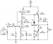
I have been thinking of building a tube headphone amp with the ability of driving a wide range of headphones . Class A most of the time but capable of higher voltages and currents if needed in class AB mode.
I will attach a circuit that I checked out with Spice. It seems OK. Any comments or suggestions from anyone before I build a prototype , is welcome.
The supply has been restricted to 150 volts and the output MOSFET's are working in Class A mode for currents of less than 11mA.
Cheers.
I will attach a circuit that I checked out with Spice. It seems OK. Any comments or suggestions from anyone before I build a prototype , is welcome.
The supply has been restricted to 150 volts and the output MOSFET's are working in Class A mode for currents of less than 11mA.
Cheers.
Attachments

Tube sake?
Hi John,
I must admit this is for 'tubes' sake ! Actually I have built so many discrete and opamp based headphone amps in the past I am 'hoping' that this may sound better.
It could be more like let me build this and see how good it is - I have had a good time with valve based circuits. I also admit that not all valve circuits are better than solid state circuits.
In my circuit I goofed the feedback part of it. Having a 47K resistor in series with the input must be a really terrible thing to do with respect to noise. But being a line level stage I am currently ignoring it. The feedback component values are not right and I will post another message after I check it out.
Don't you think it is interesting to see how this will sound ?
I can rig this up in a day!
Cheers.
6DJ8
Hi Frank,
I know the 6DJ8 is much better at low voltages. I did this so that I could find some use for the dozens of ECC82's that I have ! I have very few 6922's that I got from Singapore. Those are reserved for better applications. The low voltage was chosen to use less expensive supply components and to cut dissipation on the MOSFET's.
In the Spice simulation the distortion of this circuit is quite low but this need not necessarily tell us how it sounds. Only way to get a conclusive idea is to build one. This is not a best of components or circuit configuration . Just wanted to use the ECC82 for a class A headphone amp. With the MOSFETS loading it the distortion should not go up too much.
Cheers.
Power.
I was aiming for about 10mW into 100 ohms (class A ) . That would also be enough for a 92db/300 ohms phones that I have.
I also have a 92db/40 ohms Audio Technica. For normal listening it should be in the class A range. I do not blast my headphones - cannot afford to kill my hearing.
I just found that the April 1999 issue of Glass Audio has a Tube/MOSFET headphone amplifier design. Wonder what it is like. Does anyone know? In any case I will build this one and let you guys know what it is like.
Thanks for all the feedback.
Cheers.
Thanks,
300 Ohms 10mW can be quite enough (safe)
This kind of hybrid, I imagine, can Sound very good,
either you use BIPOLAR with low distortion
or MOSFET configuration at the output.
I think I had a quick look at the project you mention,
in Glass Audio archives. There are some good articles there.
300 Ohms 10mW can be quite enough (safe)
This kind of hybrid, I imagine, can Sound very good,
either you use BIPOLAR with low distortion
or MOSFET configuration at the output.
I think I had a quick look at the project you mention,
in Glass Audio archives. There are some good articles there.
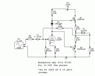
Circuit update
I have figured out another scheme for this amp. The tube is a resistor loaded gain stage. The output is a class A/ AB stage to drive the headphone . The unit can also be used as a preamp with a gain of around 5. Into high impedance loads or low voltages into low impedance phones the stage should work in class A mode.
The distortion seems to be less than about 0.1% when I simulated it in Circuitmaker. Now I have to build the unit to test its real performance. Not ethat in place if the anode load resistor we can use a current source which cuts down the distortion by a factor of 4 or so. It will be necessary to build this unit to find out if that makes an audible difference.
Any comments ?
Cheers
Attachments
Some details
The input impedance is not obvious from the circuit as it uses voltage shunt feedback and the gain of tube stage is not very high.
It seems to be in the 100K ohm range as I checked in the Circuitmaker simulation. The output stage quiesent current can be changed by varying the two source resistors. I used IRF 640/9640 because that's what we get here. The tube as explained earlier is because I have so many of them.
The output capacitor needs to be higher for lower impedance headphones. It should be rated higher than 100 volts and so could be a problem size wise and quality wise. I will build mine and post the results later.
Cheers.
If you remove R2 the 330k resistor , the circuit will have no negative feedback but will still work fine. Might be interesting to see how it sounds compared to the feedback version. There will be earlier rolloff but it may not be so audible and distortion on paper is higher.
Amp design
Hi Halojoy,
I wanted the circuit to be useful as a preamp and a headphone amp for a range of impedances. I have a range of phones from 32 to 600 ohms.
I will have this design built by this weekend. I have some decent measurement equipment and will put up the results as soon as I complete the tests.
Should be interesting.
I wanted to simulate the design with the 6DJ8 or 6922 but I do not have the Spice data that is useable with Circuitmaker .
Cheers.
Re: Amp design
They can work as lineamps, with great drive capacity downto the "magical" 600 ohms. 1mW in 600 ohms= 0.77459 Vrms, some kinda old standard
Yes, that is a the good thing with headphone amps.ashok said:Hi Halojoy,
I wanted the circuit to be useful as a preamp and a headphone amp for a range of impedances. I have a range of phones from 32 to 600 ohms.
I will have this design built by this weekend. I have some decent measurement equipment and will put up the results as soon as I complete the tests.
Should be interesting.
I wanted to simulate the design with the 6DJ8 or 6922 but I do not have the Spice data that is useable with Circuitmaker .
Cheers.
They can work as lineamps, with great drive capacity downto the "magical" 600 ohms. 1mW in 600 ohms= 0.77459 Vrms, some kinda old standard
=0dBm1mW in 600 ohms= 0.77459 Vrms, some kinda old standard
Still in use, but more often used is dBu
This is the unterminated equivalent.
")
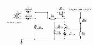
Circuit update
Hi Bob,
I had a look at the circuit you refered to. Yes it looks fine and it uses batteries keeping the 'ripple' problems away. Unfortunately I cannot find those tubes here and lantern batteries are not so common here.
I looked the circuit I put up earlier and found that like many low feedback design's this has very poor ripple rejection. I wanted at least 80db ripple to signal ratio ( at 1mW into 300 ohms). So I had to design a low ripple regulated power supply and this was not enough. So I modified the circuit some more and the result is shown in the diagram below.
The anode load has been split into two resistors with a capacitor going to ground. This cuts some of the supply induced ripple and the capacitor across across the cathode resistor which increases the stage gain a bit and cuts ripple by increasing the apparent negative feedback.
I am building the circuit and will put up the results soon.
Cheers.
Note V4 is the 'ripple' supply used in the simulation and is not normally part of the circuit. The input signal has been set to 'o' volts. In Circuitmaker this simulation gave a s/n of about 84db with respect to 0.5V rms output.
Attachments
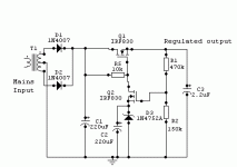
Regulated supply
I simulated this supply circuit and its performance seems to be good enough.
I anyone has any suggestions please let me know before I build this circuit.
The passive component values may change a bit when it is finally done.
Cheers.
I simulated this supply circuit and its performance seems to be good enough.
I anyone has any suggestions please let me know before I build this circuit.
The passive component values may change a bit when it is finally done.
Cheers.
Attachments
Built and tested
Hi, I finally completed the amp after several problems and blown MOSFET's.
I am attaching the frequency response measurement. The amp is essentially flat without a load. With a fluctuating load like a headphone the response is withing +/- 0.3 db from 20 to 20 Khz.
The sound is very good over headphones. The transients are fabulous and bass goes deep with a Sennheiser HD-580 headphone.
More details later along with a picture.
Cheers.
I tried the Sheffield Drum CD and Linda Ronstadt - Winter Light. Have not had time to try other disc's.
Cheers.
Attachments
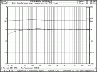
Response graph.
The response graph has three curves. The one at 0db is the amp into an open load. The next lower one is into a 300 ohm HD-580 headphone and the lowest one is the response into a Sennheiser HD-475 60 ohm headphone.
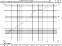
The distortion curve attached below is into a 150 ohm load. The kink around 2 volts is probably the region where the amp goes from class A into class AB operation. Note that most of the signal is below this ( less than 1.5 volts peak ) when listening to music on headphones. Into high impedances of 5K ohms or higher , the amp is essentially in the class A mode. Distortion is not very low as the feedback is quite low. I will test the same circuit with the 6922 tube and post the performance.
Note that the noise floor is quite low around -80db and is quite inaudible on the headphones.
Cheers.
The response graph has three curves. The one at 0db is the amp into an open load. The next lower one is into a 300 ohm HD-580 headphone and the lowest one is the response into a Sennheiser HD-475 60 ohm headphone.
The distortion curve attached below is into a 150 ohm load. The kink around 2 volts is probably the region where the amp goes from class A into class AB operation. Note that most of the signal is below this ( less than 1.5 volts peak ) when listening to music on headphones. Into high impedances of 5K ohms or higher , the amp is essentially in the class A mode. Distortion is not very low as the feedback is quite low. I will test the same circuit with the 6922 tube and post the performance.
Note that the noise floor is quite low around -80db and is quite inaudible on the headphones.
Cheers.
Attachments
- Status
- This old topic is closed. If you want to reopen this topic, contact a moderator using the "Report Post" button.
- Home
- Amplifiers
- Headphone Systems
- Hybrid tube headphone amp design