Re: heahphone amp
you have something good going here
very interesting idea!

.................................................
Three things:
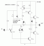
1. Better use N-JFET. Much much easier to find. Better price.
I also think generally speaking, N-JFET are better peformance than P-JFET.
You simply have to turn a few thing upside down in your circuit.
But can keep most values the same.
2. Only a few uA operation in JFET.
I do not think it will work well at such low current level.
At least 0.2 mA, maybe you need even 0.5-1.0 mA for good linearity.
To set current in JFET, you use a resistor B-E (Base-GND) at T3.
2k2 will give ~0.3 mA in JFET.
At same time this change would make ( 10k x 0.3 mA = ) 3 Volt drop across R10.
And so you would need to adjust DC voltage at JFET gate.
Change R8/R9 a bit to get output at 15 Volt.
3. Choice of transistors in output. TIP29/30.
I do not remember how much power they are for. But you will not often see them.
Think they are slow.
I am sure they will work alright, if you have no other.
But There are better choices.
- Often used for lower power audio are TO-126 case: BD139/140 or MJE340/350.
- Think also MJE15030/15031 (TO-220 case) could do very nicely.
Good circuit, after a few changes!

audiofan said:I would like to build an heaphone amp and I have desing this circuit with parts I have, does somebody see big flaw in this desing
you have something good going here
very interesting idea!
.................................................
Three things:
1. Better use N-JFET. Much much easier to find. Better price.
I also think generally speaking, N-JFET are better peformance than P-JFET.
You simply have to turn a few thing upside down in your circuit.
But can keep most values the same.
2. Only a few uA operation in JFET.
I do not think it will work well at such low current level.
At least 0.2 mA, maybe you need even 0.5-1.0 mA for good linearity.
To set current in JFET, you use a resistor B-E (Base-GND) at T3.
2k2 will give ~0.3 mA in JFET.
At same time this change would make ( 10k x 0.3 mA = ) 3 Volt drop across R10.
And so you would need to adjust DC voltage at JFET gate.
Change R8/R9 a bit to get output at 15 Volt.
3. Choice of transistors in output. TIP29/30.
I do not remember how much power they are for. But you will not often see them.
Think they are slow.
I am sure they will work alright, if you have no other.
But There are better choices.
- Often used for lower power audio are TO-126 case: BD139/140 or MJE340/350.
- Think also MJE15030/15031 (TO-220 case) could do very nicely.
Good circuit, after a few changes!
audiofan said:2K2 across T3 does wonderfull thing high frequency limit has almost double and square wave respose is a lot better...
i will work tomorrow on going to a n chanel fet...tank you
audiofan said:still in progress...............
will order parts semiconductors next week
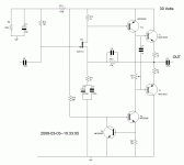
C5, you can and should attach in a more usual place.
Can be like 50-220pF, between B and C of T12.
Start with a value of 100pF.
Between Base and Collector of voltage amplification transistor T12. ( In the VAS, volt amp stage ).
C5, compensation cap, will work as you have it now, across feedback resistor.
But most designers use it as I mentioned, locally across VAS transistor.
Schematic looks basically good now.
You have done a fine job.
As I can see it will work alright like that.
There might be only small final trimmings, changes to some resistor values.
To get the best possible performance.
==========================================
If you want to see a similiar preamplifier, this will be 'DOZ preamp'.
By Rod Elliott at http://sound.westhost.com/
It is basically same idea as your amp. But no output stage.
Death of Zen Preamp.
Minimalist Discrete Hi-Fi Preamp - ESP Project 37:
An externally hosted image should be here but it was not working when we last tested it.
He also has a DoZ Headphone Amplifier. Project 70:
An externally hosted image should be here but it was not working when we last tested it.
- Status
- This old topic is closed. If you want to reopen this topic, contact a moderator using the "Report Post" button.

