I'd like to make a relatively simple and compact OTL headphone amplifier for driving high impedance headphones, Sennheiser HD600s to be precise.
So as to have something to start from, I'll (over)specify initially a maximum output of 10V into 300 ohms. That's 33 mA current and 28V swing peak-to-peak. I wont specify gain or output impedance.
As I see it there are at least three routes, albeit interelated.
1. triode voltage stage + cathode follower
c.f. A Single-Ended OTL Amplifier for Dynamic Headphones
http://headwize.com/projects/showfile.php?file=waarde1_prj.htm
2. The Morgan Jones, triode voltage stage + White follower
c.f. The Morgan Jones Mini Tube Headphone Amplifier
http://www.headwize.com/projects/cmoy5_prj.htm
3. Mu follower
c.f. An OTL Tube Headphone Amplifier
http://headwize.com/projects/showfile.php?file=strain1_prj.htm
I happened to pick references from headwize, but there are plenty others floating around the net.
I was reading up on the optimization of the White follower by John Borskie, when I was struck by his comments about underestimating the static current required for driving low impedance loads.
http://www.tubecad.com/october99/
And finally, there is the classic article on the mu follower by Alan Kimmel, which argues the advantages of the pentode and MOSFET as the CCS gain element.
http://www7.taosnet.com/f10/mustage.html
Comparing the three designs, I cant see that (1) has much going for it other than conceptual simplicity. (2) is pretty neat, especially the optimized version, and I was half way to getting the parts when I started thinking about (3), and especially with a MOSFET. That would be a one-tube (dual triode) for a stereo amp .. a long time holy grail of mine, just for the zen of it.
Searching some of the forums including this one I couldn't find any documented implementation of the mu-follower as a headphone amp with either a pentode or a MOSFET as a CCS.
Question 1. Anyone know of any such projects on the net?
As I see it, OTL tube headphone amplifiers are a bit of a waste in that the available voltage swing is far beyond anything remotely needed, so you end up blowing a lot of power maintaining the B+ at 200V for an output swing that will never exceed 1/10th of that. The problem is compounded as you increase the current to coerce the tubes into producing a low output impedance.
The mu-stage is nice in that the current though the CCS can be increased independently of the plate current flowing through the triode. Since the plate resistor of the triode is effectively infinite, it also frees the plate voltage of the tube from the B+, such that the plate voltage can be set much closer to the B+ without compromising linearity. Last, since the output voltage swings are so small, the plate voltages can be much lower than when designing a driver stage for a 300B, say.
The idea on paper then use a MOSFET / 6SN7 (6CG7) mu-follower with a low B+ of 150V or so, with the plate of the triode at about 100V. 15-20 mA of current would be drawn though the MOSFET, but only 4-6 mA of current would go through the triode. In theory: Plenty of available output current without stupid amounts of heat dissipation.
Question 2. If there is something wrong, please let me know now.
/RJM
Attachments
![figure3-4[1].gif](/community/data/attachments/40/40371-b88fdd51f4daeffe10c9678f5b18a154.jpg)
You might be interested in the SOHA project over at Headwize. Basically a 12AU7 driving an OPA2134; one variant is a mu-follower.
http://headwize.com/ubb/showpage.php?fnum=3&tid=5896&fpage=1
http://headwize.com/ubb/showpage.php?fnum=3&tid=5896&fpage=1
I built one loosly based on this. http://headwize.com/projects/showfile.php?file=ahammer2_prj.htm
Dead silent and open. I used 4 triodes for the catode follower because of 64 ohm cans with no problem. The differential input satisfied my SS beginings and maintains phase unlike most of the other designs. This was important for me because I didn't want to hack into the cans to reverse the wires (common ground)
Here's some stuff about it. http://www.diyaudio.com/forums/showthread.php?s=&threadid=67863
Thanks!
That circuit brings up a number of neat concepts. Very low plate voltages. Voltage doubler. Last but not least, the depletion mode MOSFET (LND150) simplifies the circuit considerably ... and it has a much lower input capacitance than the IRF720 I was looking at earlier.
Adding the solid state buffer drives low impedance headphones and gets rid of the large output coupling capacitor ... the Achilles heal of these single ended circuits i.m.o.
The downside is the (slight) complication to the power supply.
I would still like to drive the HD600s from the mu-follower directly, I think. With the LND150 the transconductance and power limitations imply a rather high output impedance and low output current, unless I parallel a bunch of them, so some modification of the front-end presented is in order.
Using a 2134 to buffer the output ... I dunno, I guess I just feel that if I wanted to listen to an op-amp I'd build a ChuMoy and be done with it.
/R
rjm said:Using a 2134 to buffer the output ... I dunno, I guess I just feel that if I wanted to listen to an op-amp I'd build a ChuMoy and be done with it./R
I'm a total newb when it comes to amp building, but I've built CMOY's and the mu-follower SOHA, and the SOHA sounds absolutely nothing like a CMOY. You can vary the sound of the SOHA so many ways. Every tube I've tried has sounded completely different from the last, and I've tried many different 12AU7's and thier variants. I think you would be pleasantly surprised with the sound it produces and for no more than it costs your not really out much. It only costs about $20 than the first CMOY I built and that's having to order every little part for it.
the SOHA sounds absolutely nothing like a CMOY
I didnt mean to imply that it would. Just that if it was using the same op-amp circuit to drive the 'phones, the SOHA was only adding distortion via the tube stage, its not any different from the ChuMoy so far as being able to drive the load is concerned.
Your comments regarding the different sound of different versions tend to confirm my suspicions.
That's not so say the SOHA isnt a good amp. I happen to think a good helping of 2nd harmonic and a bit of tone shaping is actually a good thing for a headphone amp to have.
-R
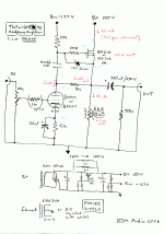
Since it seems like it hasn't been done before in quite the same way, I'm giving the circuit a name and posting it.
Redrawing Alan Kimmel's original mu-follower schematic, I was struck by how much it looks like a Szekeres headphone amp driven by a triode. The MOSFET in the case of a mu-follower is far more elegant as it is both a constant current source for the plate as well as a source follower for the load.
Once upon a time I used a JFET to drive a Szekeres and enjoyed the results very much. Combining a MOSFET follower with a 6SN7 looks like way more fun...
(Both the Szekeres schematic and my version are archived at headwize, here.)
/R
P.S> the 0.022uF cap should also be rated to 250V, while the 22uF cathode bypass can be 10V.
Attachments
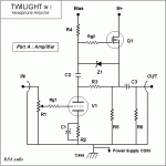
I've started writing up this project. Details at the Twilight Headphone Amplifier page.
Building a prototype is next on the "to do" list. Besides how it sounds, I'm interested in seeing how compact it can be made.
/R
Building a prototype is next on the "to do" list. Besides how it sounds, I'm interested in seeing how compact it can be made.
/R
Attachments
Thought I'd put this thread to bed properly... ")

The Twilight headphone amp (with HD600s) has become my long term reference and diagnostic tool. 2 years and some, and I have still to find a weakness or even a defining sonic trait at all. It appears for all intents and purposes to be input=output, proving again and again to be as least as good as whatever source I throw at it.
Highly recommended, but maybe not for beginners...
I've started writing up this project. Details at the Twilight Headphone Amplifier page.
Building a prototype is next on the "to do" list. Besides how it sounds, I'm interested in seeing how compact it can be made.
/R
Unfortunately this link is death.
This topology is also suitable as driver stage for single ended and PP power follower - so I think
- Status
- This old topic is closed. If you want to reopen this topic, contact a moderator using the "Report Post" button.
- Home
- Amplifiers
- Headphone Systems
- mu-follower hybrid headphone amplifier