Apologies in advanced for my noob questions.
I'm looking for a schematic, or possibly assistance in modifying an existing one, to build a headphone amplifier using 6SN7 and 6080 tubes. I have a quite a few NOS RCA 6080's laying around along with a few 6SN7/12SN7's (and a few 6SL7GT's, not sure if they're useful for this).
I've seen various preamps utilizing the 6SN7, and I've seen a tubed headphone amp schematic on headwize using a 6922 + 6080/6AS7 I assume for gain and as a cathode follower, respectively. I'm not sure if I can just plug the cathode follower on to other schematics (I'm still learning/trying to understand tube design.. Please forgive me")
I've also thought that maybe paralleling the triodes of the 6080 for more current drive might be desirable, since I'd like the amp to be usable with my grado cans as well has my AKG and Sennheisers.
I know there are a few commercial designs out there using the 6SN7 for the gain and paralleled 6080's for the output (I believe that one of them uses an output transformer as well). I'd like to try it OTL first, and then maybe move on to investing in iron if the performance gains would be worth it.
Any suggestions or pointers or schematics would be most helpful!
Thanks,
M1
I'm looking for a schematic, or possibly assistance in modifying an existing one, to build a headphone amplifier using 6SN7 and 6080 tubes. I have a quite a few NOS RCA 6080's laying around along with a few 6SN7/12SN7's (and a few 6SL7GT's, not sure if they're useful for this).
I've seen various preamps utilizing the 6SN7, and I've seen a tubed headphone amp schematic on headwize using a 6922 + 6080/6AS7 I assume for gain and as a cathode follower, respectively. I'm not sure if I can just plug the cathode follower on to other schematics (I'm still learning/trying to understand tube design.. Please forgive me
I've also thought that maybe paralleling the triodes of the 6080 for more current drive might be desirable, since I'd like the amp to be usable with my grado cans as well has my AKG and Sennheisers.
I know there are a few commercial designs out there using the 6SN7 for the gain and paralleled 6080's for the output (I believe that one of them uses an output transformer as well). I'd like to try it OTL first, and then maybe move on to investing in iron if the performance gains would be worth it.
Any suggestions or pointers or schematics would be most helpful!
Thanks,
M1
Here's one... this was commercially available for a while. There is a schematic on the last page that's fairly readable.
http://www.pmillett.com/Wheatfield/manual.pdf
The power transformer was a Thordarson 26R160 - you can use a Hammond 270HX (or 370HX, I used them for export 220V versions) as well. The choke was 5H 200mADC.
I'd suggest using PP-in-oil motor run caps for the output caps, and a BIG wirewound for the 6080 cathode load resistor - no power films, they get noisy over time.
Pete
Depending upon what phones you are driving, you can also use a single 6as7g with a plate load ccs and take the output from the plate. This is Pete's low mu preamp design, and with a 6as7g the output impedence should be low enough (~300 ohms) for sennheisers. You could also AC couple the output to a transformer or a solid state buffer like the szekeres ... or parallel a couple of tubes to lower the output a bit.
I agree with Pete on the caps. You can get ASC's from Alied or percy or partsconnexion. I tried them as output caps and had pretty good results.
I agree with Pete on the caps. You can get ASC's from Alied or percy or partsconnexion. I tried them as output caps and had pretty good results.
It actually sounds pretty decent with Grados (32 ohms), especially if you up the output cap from 47uF to more like 100uF to help bring up the LF response. It's a matter of taste: I find Grado's a bit too edgy, and the lower damping factor improves things to my ears.
If you don't mind generating lots of heat, you can also parallel two 6080 sections per channel - just drop the cathode load resistor by a factor of 2 and double the wattage.
Or build it as-is, then swap in a 6528A or 5998... they will lower the Zo. My favorite is the 5998A.
We shipped the "premium" version of the amp with a 6528A. It got very hot, though... 5A filament!
Pete
I built an OTL head phone amp using long tail pair input 6DJ8 to a cathode follower, 2 tubes 5687 paralleled (4 triodes) and it drives my 64 ohm Sennheisers louder than I care to listen. And the LTP input keeps the phase right. It's loosly based on http://headwize.com/projects/showfile.php?file=ahammer2_prj.htm but the PSU is a little beefier and the output section is like the doulbed one with the higher dissapation 5687's.
Work's very busy for the next week, but I could scrach out the schematic if you'r interested.
Work's very busy for the next week, but I could scrach out the schematic if you'r interested.
Attachments
pmillett said:It actually sounds pretty decent with Grados (32 ohms), especially if you up the output cap from 47uF to more like 100uF to help bring up the LF response. It's a matter of taste: I find Grado's a bit too edgy, and the lower damping factor improves things to my ears.
Grado's, at least their better ones, kill my ears with solid state. On a millett, my HF-1 sounds great. I know it's not the be-all end-all amp, but dang it, I love and and use it all the time on my computer.
pmillett said:
If you don't mind generating lots of heat, you can also parallel two 6080 sections per channel - just drop the cathode load resistor by a factor of 2 and double the wattage.
Or build it as-is, then swap in a 6528A or 5998... they will lower the Zo. My favorite is the 5998A.
We shipped the "premium" version of the amp with a 6528A. It got very hot, though... 5A filament!
Pete
Does doubling the 6080 sections also lower the Zo by half? Or am I mistaken on that?
I think I might go with the paralleled 6080 sections since I have like 14 NOS RCAs laying around here that I'd like to use.
Can you recommend any sources for the caps you listed? Or could I use some large solens from Parts Express?
Thank you all for the help. I'm pretty psyched to build this project now!
motherone said:Can you recommend any sources for the caps you listed? Or could I use some large solens from Parts Express?
I listed 3. You want more?
Solens will work as well, but they will not sound as good.
I have two comments:
1) www.tubecad.com
2) For headphones, you don't need squat for gain. In fact, depending on your source, all you really need is a follower. Leave the 6SL7s in the drawer. Use the 6SN7s.
Grey
EDIT: (My brain is addled tonight and I'm forgetting things.) You're playing music from a computer and blaiming the amp/headphones for being bright?
What's wrong with this picture?
Oh, blast and bother...forgot something else...
Yes, doubling the outputs will halve the Zout, all other factors being equal. However, given that you'll need very little gain, you'll likely be using some of the gain as NFB and this will drop the Zout too.
But...
Headphone diaphragms being as low in mass as they are, very little damping factor is actually required. Not to mention that damping factor is largely overrated, witness some tube amps (e.g. the old CJ Premier One) that had absolutely butt-kicking bass, whereas some solid state amps with far, far better damping factors sound bloated and uncontrolled by comparison.
Grey
pmillett said:
can 6sn7 be substituted with ecc99? what changes to the circuit are needed? got a spare ecc99
can 6sn7 be substituted with ecc99? what changes to the circuit are needed? got a spare ecc99
you can use 6fq7/6cg7 without any circuit changes in place of 6sn7...i suspect you can get away with an ecc99 also...
It actually sounds pretty decent with Grados (32 ohms), especially if you up the output cap from 47uF to more like 100uF to help bring up the LF response. It's a matter of taste: I find Grado's a bit too edgy, and the lower damping factor improves things to my ears.
If you don't mind generating lots of heat, you can also parallel two 6080 sections per channel - just drop the cathode load resistor by a factor of 2 and double the wattage.
Or build it as-is, then swap in a 6528A or 5998... they will lower the Zo. My favorite is the 5998A.
We shipped the "premium" version of the amp with a 6528A. It got very hot, though... 5A filament!
Pete
Goodmorning to everyone
Apologize for interrupt in this kind of "old" but exciting thread
I want to build a headphone amp too and I have search around the internet for some time to find schematics for a novice like me
Someday I stumbled over the Wheatfield HA2 by Mr. Pete Millet, and then I also have found this nice thread regarding this nice amp
I would really like to try to build this amp. (I haven't ask Mr. Millet for permission yet but I will do that)Now, my phones are Sennheiser HD570 which I believe are 64 ohm and far as I understand a little too low for the HA2 to sing perfect - To make sure I have understod this correct: If you parallel two 6080 sections for each channel, it would be able to drive 32 ohm and in my case 64 ohm?
Drop the cathode load resistor: Would it be for say left channel the R14, and make it 1k instead of 2k?
How about the plate resistor - Can it be the same 10ohm for both plates or would it require two of those?
Again with the gridstoppers, is it enough with one 100ohm resistor for both grids, or will it need a 100ohm resistor for each grid?
If these changes are made and the amp operates with two parallel triodes for each channel, is it possible to go with 5998A tubes instead of the 6080 tubes without any further changes in the circuit?
I really look forward to read some reply's from you good people and make some building
Best regards from Vingborg
Denmark
Hi,
At a typical operating point the 6080/6AS7G has an internal resistance of 280R.
If you put both section in parallel then the internal resistance is halved thus giving 140R.
So this would roughly be the output impedance of your circuit where the output is taken from the anode.
Cathode and anode resistors can be halved in value (since they are in parallel) but their wattage needs to be doubled.
Gridstoppers remain the same value, just tie the signal input ends together .
At least that's how I usually do this but you could also just strap the grids together and consider them a single element. In that case gridstopper value should be double that of a single valve.
This is not critical IMO.
The gridleak resistor can be as high as halve the maximum value for a single triode.
Yes. 5998A and 6528A are drop in replacements with a bit higher gain. Check heater current though.
Keep in mind that none of the above power tubes are twin triodes but dual triodes, IOW they are not matched.
IME experience it is best practice not to use output tubes with too widely differing characteristics as current hogging may occur quite easily. (One triode glowing red hot while the other is hardly drawing any current etc).
If it were me and I needed the extra power I'd use single triodes such as the Russian 6S19P and select from a bunch of those.
If balanced correctly you have essentially a new valve, if one is too far off you'll end up with much more distortion and a circuit that's never really stable.
Just my experience though.
Ciao,
If you parallel two 6080 sections for each channel, it would be able to drive 32 ohm and in my case 64 ohm?
At a typical operating point the 6080/6AS7G has an internal resistance of 280R.
If you put both section in parallel then the internal resistance is halved thus giving 140R.
So this would roughly be the output impedance of your circuit where the output is taken from the anode.
Cathode and anode resistors can be halved in value (since they are in parallel) but their wattage needs to be doubled.
Gridstoppers remain the same value, just tie the signal input ends together .
At least that's how I usually do this but you could also just strap the grids together and consider them a single element. In that case gridstopper value should be double that of a single valve.
This is not critical IMO.
The gridleak resistor can be as high as halve the maximum value for a single triode.
If these changes are made and the amp operates with two parallel triodes for each channel, is it possible to go with 5998A tubes instead of the 6080 tubes without any further changes in the circuit?
Yes. 5998A and 6528A are drop in replacements with a bit higher gain. Check heater current though.
Keep in mind that none of the above power tubes are twin triodes but dual triodes, IOW they are not matched.
IME experience it is best practice not to use output tubes with too widely differing characteristics as current hogging may occur quite easily. (One triode glowing red hot while the other is hardly drawing any current etc).
If it were me and I needed the extra power I'd use single triodes such as the Russian 6S19P and select from a bunch of those.
If balanced correctly you have essentially a new valve, if one is too far off you'll end up with much more distortion and a circuit that's never really stable.
Just my experience though.
Ciao,
Goodmorning
Thanks for the answers..
The output signal will be taken from the cathode's, which I believe will put down the output impedans even further then given the opportunity to run my senns at 64ohms..
Allright, I contacted mr. Pete Millett on his privat mail, where he friendly responded and gave me this link to Head-fi.org :[wiki=http://www.head-fi.org/t/320365/pete-milletts-menace]%[/wiki]
That's an exciting headphone amp I think
But the psu is very, very big (300V 0.4A!!) and exspensive and that's why I have to ask you, diego6339: Which powersupply did you use for your amp?
The output tube is in parallel, how high is the bias current?
The cathode resistor R5: What's the wattage on that one?
I'm curious because The Menace amp I linked for, is really drawing current from the psu! Keep in mind that my phones are HD570 64ohms.. Maybe ther just have to be a big psu to drive these low z cans - Please let me hear from you guys again
Cheers,
Vingborg
First of all, I have to say that Pete Millett's design uses better operating points than mine. The problem is that the PSU and the heat dissipation are difficult to deal with. Still, if I were to build this amplifier again I would use the voltages and currents the Menace uses.
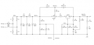
For the PSU I used a toroidal transformer with a 120 vac 1amp primary and a 6.3 vac 10 amp secondary. I used it for the high voltage which I regulated using a Maida regulator and the 6AS7 heaters where I used AC elevated to 110vdc. I also used and extra EI transformer with a regulator for the 6SN7 heater. I decided to use SS and a toroid to reduce the size and weight of the PS. Yet, the main transformer weights 7 pounds and the other over 1 pound.
The bias current in mine is 82.5 ma (82.5v / 1000ohm) and R5 is a 50 watt resistor attached to the chassis. As you can see, the Menace uses 2 resistors in parallel with a combined resistance of 1k and draws 160 ma of current for the output stage. You will have to add another 9 ma per channel for the input stage.
In my amp the cathode resistor dissipation is 6.8 watt x 2 which makes the chassis very hot. In the case of the Menace is 25.6 x 2 which would require very good heat management.
Regards,
Diego
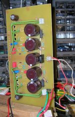
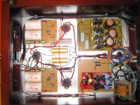
Attachments
Goodmorning
Sorry for my late answer, things are fine but fast in these days..
That was very usefull information diego6339, thank you
Maybe I'm not keeping up, but your amp and the Menace draws 82,5 ma and 160 ma. Is this for both channels or only for one channel? I don't know where to find a psu there can handle at least 350 ma 280v so I hope you tell me it's for both!! ;-)
I'm wandering - Why so high current for a parallel 6080/6as7 cathode follower, is it this particular tube which simply draws so much? I've seen headphone amps which can easily handle low z headphones and they don't seem to have a psu at this size.. Little Dot mk9 have a bias of 22 volt 65 ma (That's what I've told from the company) Well, I know it is a rare sepp circuit but still the 6080 tube!
The Bottlehead Crack dosen't look like a very big psu either, only my guess..
I would really love to build something similar to the Menace and your's, but a power supply at that size will probably be an issue to dick up..
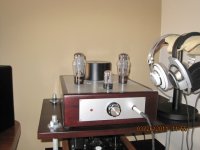
Btw, your amp is a real beauty!! I really like it
Let me hear from you again..
Best regards
Henrik
Sorry for my late answer, things are fine but fast in these days..
That was very usefull information diego6339, thank you
Maybe I'm not keeping up, but your amp and the Menace draws 82,5 ma and 160 ma. Is this for both channels or only for one channel? I don't know where to find a psu there can handle at least 350 ma 280v so I hope you tell me it's for both!! ;-)
I'm wandering - Why so high current for a parallel 6080/6as7 cathode follower, is it this particular tube which simply draws so much? I've seen headphone amps which can easily handle low z headphones and they don't seem to have a psu at this size.. Little Dot mk9 have a bias of 22 volt 65 ma (That's what I've told from the company) Well, I know it is a rare sepp circuit but still the 6080 tube!
The Bottlehead Crack dosen't look like a very big psu either, only my guess..
I would really love to build something similar to the Menace and your's, but a power supply at that size will probably be an issue to dick up..
Btw, your amp is a real beauty!! I really like it
Let me hear from you again..
Best regards
Henrik
They draw that per channel plus you have to add some for the driver. As you say, you will need around 350 ma for the Menace.
6AS7/6080 tubes are rated for 125 ma per triode. If you run the tube with too little current the circuit will have more distortion and higher output impedance. I am running my amplifier at 41 ma per triode which could be too low while the Menace is operating at 80 ma per triode. The other reason for that operating point is to better couple with the driver stage. In the case of my amplifier the bigger compromise is there, it has too little current and voltage across it.
The power supply I posted can be modified for the higher voltage and current. I took advantage of the main's stability here to work with very little voltage drop across the irf840 allowing me to use a small heatsink. You would have to plan for much bigger ones.
Regards
Hello
Hmm all of this gives me something to think about, I must say.. I'm glad I haven't ordered any parts yet
I really appreciate your help and answers
I will try and read some more stuff about cathode follower's and maybe the White cathode follower, but that's another story I guess..
Best regards
Vingborg
- Home
- Amplifiers
- Headphone Systems
- Headphone amp using 6SN7 + 6080?