I have measured the voltage output from the Trafo (no load) and i get 15V. This is not correct is it, it should be 30V
I am using the standard amveco transformer and am trying to get my head round the issue of primary and secondary configurations with regard to 230V operation. I have wired the primary in series configuration as highlighted in on the Amveco website and in the earlier post, but i am convinced that the secondary configuration needs to changed also in order to get 30V out,
Is it coincidence that i am getting 15v output due to wiring configuration or did I fry one windings (by turning the trafo into a small heater") )before I realised that i needed to modify the primary to work work with 230V and not 110?
)before I realised that i needed to modify the primary to work work with 230V and not 110?
i will also check for shorts when i get back from work.
mark
I am using the standard amveco transformer and am trying to get my head round the issue of primary and secondary configurations with regard to 230V operation. I have wired the primary in series configuration as highlighted in on the Amveco website and in the earlier post, but i am convinced that the secondary configuration needs to changed also in order to get 30V out,
Is it coincidence that i am getting 15v output due to wiring configuration or did I fry one windings (by turning the trafo into a small heater
)before I realised that i needed to modify the primary to work work with 230V and not 110? i will also check for shorts when i get back from work.
mark
D1GGY said:I have measured the voltage output from the Trafo (no load) and i get 15V. This is not correct is it, it should be 30V
I am using the standard amveco transformer and am trying to get my head round the issue of primary and secondary configurations with regard to 230V operation. I have wired the primary in series configuration as highlighted in on the Amveco website and in the earlier post, but i am convinced that the secondary configuration needs to changed also in order to get 30V out,
Is it coincidence that i am getting 15v output due to wiring configuration or did I fry one windings (by turning the trafo into a small heater
i will also check for shorts when i get back from work.
mark
Hi Mark,
Make sure your secondaries are wired in series, and that the point where you join the secondaries (the center tap) is connected to the center "GND" pin on the power header/connector.
Cheers!
Russ
brown & red connected together - brain failure the likely cause!!
You have got me thinking........
i may have measured quite correctly 15V between the centre pin and each of the phase (hot) pins and not engaged brain before opening mouth.....(for some reason expecting 30V)
I will check tonight and go from there before i disapear in ever decreasing circles
m
You have got me thinking........
i may have measured quite correctly 15V between the centre pin and each of the phase (hot) pins and not engaged brain before opening mouth.....(for some reason expecting 30V)
I will check tonight and go from there before i disapear in ever decreasing circles
m
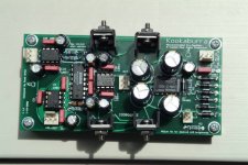
OK, I have noticed one thing, One of my caps (round one next to C20) is the otjher way round to the example on the twistedpear website, mine is soldered as per the PCB detail, has ths been changed in the design at all?
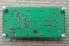
I have also included the image below, any thing obviously wrong looking at this?
I have also included the image below, any thing obviously wrong looking at this?
Attachments
OK I do not want to trash this thread by going through how to repair a kook after some muppet not installing the components correctly trashed his, but how might i go about fixing my cooked kook....
The diodes are now installed correctly, I measured the output voltage on the voltage regulators and two read 19V +- and one 12V one 5V so i assume two are trashed, these i will replace but what else is likely to have become fit for the bin?
Am i better getting another kit at this point and learning to read?
Mark
D1GGY said:OK I do not want to trash this thread by going through how to repair a kook after some muppet not installing the components correctly trashed his, but how might i go about fixing my cooked kook....
The diodes are now installed correctly, I measured the output voltage on the voltage regulators and two read 19V +- and one 12V one 5V so i assume two are trashed, these i will replace but what else is likely to have become fit for the bin?
Am i better getting another kit at this point and learning to read?
Mark
I well I think the worst case would probably be that you would need to replace all the other ICs. That would be the PGA, two opamps, and the PIC. You would also want to test each of the caps to make sure that they have not become a short.
Sorry for your bad luck, I have made many similar mistakes myself.
Cheers!
Russ
Hi Russ,
I think i will put this down as a test Mule and retire it!
Look out for a nother order on the website as i do not have the ability program the PIC, additionally i do not have the test equipment to work through the other items and would probably end up chasing my tail.
This is what comes from trying to solder with a screeming ten day old boy in the same room!!
cheers, mark
I think i will put this down as a test Mule
and retire it!Look out for a nother order on the website as i do not have the ability program the PIC, additionally i do not have the test equipment to work through the other items and would probably end up chasing my tail.
This is what comes from trying to solder with a screeming ten day old boy in the same room!!
cheers, mark
Ouch... The attenuator chip is such nice thing to let the magic smoke out of.
On the NEXT one you build you might want to employ a power up method common in PCB Kit building instructions.
Build the power supply section first and without ANY other IC's installed... check the voltages. If they are good... *then* continue knowing that you won't fry anything when you power up.
On the NEXT one you build you might want to employ a power up method common in PCB Kit building instructions.
Build the power supply section first and without ANY other IC's installed... check the voltages. If they are good... *then* continue knowing that you won't fry anything when you power up.
The attenuator chip didn't even give me that much entertainment , A puff of smoke would have been something!
cheers i will do the power side of things first in future, i guess i was lucky with the Rev C ----- built it ----switched on ---- great sound haa haa haa
I am not used to small voltages and micro amps, I normally work on High Voltage networks and many Hundreds of amps......Scary to think about really.....
what is the best method for desoldering, sucky thing or braid?
Oh and thanks Brian......
mark
, A puff of smoke would have been something!cheers i will do the power side of things first in future, i guess i was lucky with the Rev C ----- built it ----switched on ---- great sound haa haa haa
I am not used to small voltages and micro amps, I normally work on High Voltage networks and many Hundreds of amps......Scary to think about really.....
what is the best method for desoldering, sucky thing or braid?
Oh and thanks Brian......
mark
D1GGY said:
what is the best method for desoldering, sucky thing or braid?
mark
A desoldering pump works nicely, braid works well too, but I mostly use that for SMD devices and such.
You'd be surprised what can survive this type of mistake. I made several big ones on mine and only ended up frying my PIC. I had switched the LM812 and 912. Just swapping them corrected things w/o any damage. I also connected the transformer to the pot connector. That fried the PIC, but everything else was A-OK.
Thats good to hear,
I still do not understand why i messed it up in such a spectacular manner, still nothing actually went bang!
I have had a mad couple of days and have really thrown some abuse at it
> I have applied over voltage to it through incorrect primary wiring
> Inverted voltage applied to it due to reversed voltage regulators
> Goodness only knows through incorrect bridge configuration
> Loads of temperature from my soldering iron in futile attempts at desoldering....
all good fun though, and will be fixed, just glad i did not attach my Senn HD25's to it......
Ummm Could Twisted Pear maybe use you as a tester? You know, like the way they used to show us how AT&T would stress their phones to be sure they would hold up under normal use?
I prefer the SOLDER SUCKER, myself. I've had a EDSYN DS 017 (AKA SOLDAPULlT) since 1978 and it STILL does an excellent job. The board might be saved if you try.
Good Luck
I prefer the SOLDER SUCKER, myself. I've had a EDSYN DS 017 (AKA SOLDAPULlT) since 1978 and it STILL does an excellent job. The board might be saved if you try.
Good Luck
I think I need more sleep actually......
I think I have demonstated how robust the Twisted stuff is to abuse, I am in no doubt that it will be up and working soon.
I am more than happy to test future products for idot proofing!!!
I really do not know what happened here, I do not normally suffer in this maner.
As Testament, my solder sucker is from my apprenticeship days as a prototype wireman and is still going strong. With the above public demonstration it would have been lucky to have lasted 6 months
I am hopeful that the board is recoverable and intend to have it partnered with my Rev C's in due course.
Cheers, M
- Status
- This old topic is closed. If you want to reopen this topic, contact a moderator using the "Report Post" button.
- Home
- Amplifiers
- Headphone Systems
- Digitally controlled preamp/headphone amp