Re: Question...
Hi Russ,
Define amazing. Are we talking in the Freebird ballpark? Can you describe any feature differences in the sound between the two?
Regards,
Michael
Russ White said:
Other than that small quirk the thing sounds amazing.
Hi Russ,
Define amazing. Are we talking in the Freebird ballpark? Can you describe any feature differences in the sound between the two?
Regards,
Michael
Re: Re: Question...
I don't want to comment too much too soon, as my enthusiasm is still high, but the noise floor is lower (this you can tell right away), it just sounds faster, more transparent. There is no pot in the signal path, so none of its added noise. But its like asking me what do I like better, a stout or a porter.") I like em both.
I like em both.
If I were going to build just one, it would be this one.
Cheers!
Russ
maf_au said:
Hi Russ,
Define amazing. Are we talking in the Freebird ballpark? Can you describe any feature differences in the sound between the two?
Regards,
Michael
I don't want to comment too much too soon, as my enthusiasm is still high, but the noise floor is lower (this you can tell right away), it just sounds faster, more transparent. There is no pot in the signal path, so none of its added noise. But its like asking me what do I like better, a stout or a porter.
I like em both. If I were going to build just one, it would be this one.
Cheers!
Russ
Hey, Russ!
Don't feel bad about the signal leakage, I have seen plenty of commercial gear that does that, too.
Do they make normally-closed super mini relays? You could always short the output when the power is off. It wouldn't be in the signal path, relay current is irrelevant, but if your amp is battery-powered, then the current draw much but make it a non-starter...
Wes
Don't feel bad about the signal leakage, I have seen plenty of commercial gear that does that, too.
Do they make normally-closed super mini relays? You could always short the output when the power is off.
It wouldn't be in the signal path, relay current is irrelevant, but if your amp is battery-powered, then the current draw much but make it a non-starter...Wes
Well that is good to know Wes.
It is a very tiny signal which is passing through, barely audible.
I will check out the normally closed relay idea, I had actually used that once before, but in this case I think I should probably put a resistor beween the relay contact and ground so as not to completly short the output of the AD8620 during the brief time it is powering down.
I wonder if that would get me the desired effect....
Cheers!
Russ
The resistor is not a bad idea -- I wouldn't have thought of that!
That said, I checked the Analog datasheet for that chip. It lists "Output Short-Circuit Duration to GND .... Infinite" in the abs. max ratings section, so I don't think the resistor is strictly necessary.
Snubbing the relay with a diode is also worth considering.. but I'm not sure if the spike would happen while the amp was capable of "pop"ping your headphones.
Also, IF I'm reading the sheet right, it says the chip draws 65 mA when the output is shorted -- that may happen when the amplifier is first powered on.
Hey, check these babies out -- http://oeiwcsnts1.omron.com/pdfcatal.nsf/PDFLookUpByUniqueID/E96F438DF5E13E9B86256FC7005C765D/$FILE/D20G5LE0305.pdf
The G5LE-1's (12V, 24V) are in stock at Digikey, Allied, Sager.... and worth about three bucks. The largest dimension on this relay is under one inch. It is SPDT, so you can use one side as if it were a SPST-NC. Coil current is 400mW.
I have 280mW Omron relays that are even smaller, but the price doubles and nobody seems to have stock.
But I only spent a few minutes looking.
Wes
So far this looks like the best candidate... It only draws 200mw.
http://pdf.alldatasheet.com/datasheet-pdf/view/82419/ETC/DS2Y-S-DC12V.html
And I can get them for about $2.00US and they are not large, and I would only need one per board.
http://pdf.alldatasheet.com/datasheet-pdf/view/82419/ETC/DS2Y-S-DC12V.html
And I can get them for about $2.00US and they are not large, and I would only need one per board.
Atually now that I look a little deeper I think these DPDT
AZ847-12
http://www.azettler.com/pdfs/az847.pdf
which is equivalent to
Omron G6H-2-DC12
Are perfect.
Very small (DIP10) and low power consuption and fast acting.
And I just got some on ebay for less than a buck each.


Cheers!
Russ
AZ847-12
http://www.azettler.com/pdfs/az847.pdf
which is equivalent to
Omron G6H-2-DC12
Are perfect.
Very small (DIP10) and low power consuption and fast acting.
And I just got some on ebay for less than a buck each.
Cheers!
Russ
Hey, Russ!
> Wes, you have been very helpful.
Glad I could help, this forum has certainly been helpful to me! I'm about to complete my first decent amp, with BrianGT's boards. Chassis should be done this weekend, I'm just waiting for my shielded twisted pair and RCA jacks now. *excitement*
AZ847-12 Looks like a sweet part. I had original mentally spec'd that equivalent Omron part, but couldn't find stock on it anywhere. And I'm always reticent to recommend a hard-to-get part.
Now, let me know how it works. I actually need a decent headphone amp... neither my Carver C11 preamp nor my crappy mixer will drive my Sennheisers properly at decent listening volumes, unless I feed the mixer a really hot signal (headphone out instead of line).
I'm strongly tempted to take your circuit and pull out the amplifier component for a build. I'd actually like to get into PIC programming (I'm a software guy by trade), but not just for a volume control.
Cheers,
Wes
wes-ninja250 said:I'm strongly tempted to take your circuit and pull out the amplifier component for a build. I'd actually like to get into PIC programming (I'm a software guy by trade), but not just for a volume control.
Yeah if it had been "just a volume control" I would have skipped it too. But it is actiually more, it removes a pot from the audio circuit. The pot in my circuit is ony on the digital side and it only is read by the ADC to get a value to the the PGA2311.
This may seem obvious, but look at how the PGA2311 works, its not a pot at all, it controlls the volume with a linear resistor network, which means there is no "wiper" there is no chance for non-linear tracking, and the resistors can be high quality low noise types(metal film) instead of the carbon type you will usually get with a pot.
So, the PGA2311 is sortof like a digitally contolled stepped attenuator with a couple of opamps in the loop to boost current.
BTW my HD600s are driven quite happily by these.
No problemo.You might also checkout my Yardbirds which have an opamp(opa627 was used, but just about any single voltage feedback opamp will work) and a BUF634.
This current design(I guess I need to name it) is actually cheaper to build (even with the relay) and in my opinion so far, sounds better.
Cheers!
Russ
I would vote for the Analog Devices SSM2404 over a relay for this:
http://www.analog.com/en/prod/0,2877,SSM2404,00.html
Less current draw, lower noise, no flux, no other nasties. And designed for this application.
They are more expensive, however. Still like them more.
http://www.analog.com/en/prod/0,2877,SSM2404,00.html
Less current draw, lower noise, no flux, no other nasties. And designed for this application.
They are more expensive, however. Still like them more.
Brian and I discussed the switch and the relay, and pros and cons of each. In the end I think I will try both, but the relay version will come first because I acually think it will have the least effect on the signal.
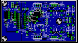
In any case, here is the new layout with the spot for the relay. In can be omitted without any ill effects(except the noted leakage with hot sources).
The leakage of the 2311 is mentioned in the datasheet, now that I have re-read it.
Cheers!
Russ
In any case, here is the new layout with the spot for the relay. In can be omitted without any ill effects(except the noted leakage with hot sources).
The leakage of the 2311 is mentioned in the datasheet, now that I have re-read it.
Cheers!
Russ
Attachments
maf_au said:Want one
Soon.... I hope.
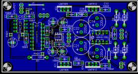
Lemme get a couple protos built first. BTW I forgot the snubbing diode for the relay, here is the corrected layout.
Attachments
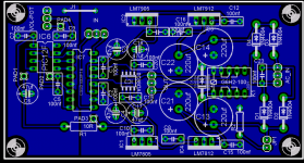
5mm pin spacing.
Thank you, I assume that these are polyster types. Smallest MKP's I can find have a ps of 7,5mm. (Epcos B32 620)
Regards
- Status
- This old topic is closed. If you want to reopen this topic, contact a moderator using the "Report Post" button.
- Home
- Amplifiers
- Headphone Systems
- Digitally controlled preamp/headphone amp