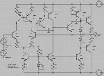
My idea is fairly simple, Q1-6 plus CCS's Q11 and Q12 form a fairly standard LTP. What makes this amp different is that instead of the standard EF or CFP output stage, Q7-10 plus CCS Q13 form a CFB amplifier canceling most of the crossover distortion before global feedback.
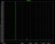
Sims give distortion below 0.000001% (mostly 2nd) THD at 1Khz, 1V into 32 ohm load. I know sims can give distortion several orders of magnitude better than real life, but even if that is the case performance should be good.
The design could be further improved with better CCS's, R6 could be replaced with a CCS, better biasing, maybe even a cascoded LTP.
It's fairly stable, though in real life it would probably need heftier miller comp.
Thoughts? Critiques?
Attachments
Allexx said:Gain=1?
Achieved with six stages

What is biasing of output stage?
I guess it is class AB, please tell me why don't you run it in class A?
I never understood why one should run headphone discrete amp in class AB.
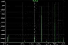
For now, yes. It's a trivial change to increase gain, simmed THD with 40db of gain (again, 1khz 1V into 32) is 0.000012%.
AC and DC impedances as seen by the LTP should be balanced as much as possible, because at this distortion level those have a significant effect.
Q1-Q2 should be matched, as should Q5-Q6 , R1-R2 and R4-R5.
Lowering Iq does not raise distortion measurably until below 1ma.
Please keep in mind that this is still all just simmed.
It's in AB for two reasons
A: so it could be battery powered
B: I think the topology could be used for power amps where class AB does have significant benifits.
P.S. Come on, six stages is nothing, people use opamps as buffers all the time.
nice than
for one 6 stages are nothing, another will use cathode follower as only active device, just a matter of taste.
I think proper compensation might be an interesting issue here.
You use two common emitter CCS-loaded stages. I think the first one is pretty fast (without Cmiller) because is driven by a low output Z buffer, so natural miller efeect is redused here, it is maybe not the best place for dominant pole.
The second local loop probably does not need any inner compensaion I think.
Just thoughts...
regards
Thanh, as Duo said Q7 is a differential amplifer, Q7-9+Q13 form a current feedback amplifier just like the "Single Transistor Input Stage" here on ESP audio.
CFB amps have the advantage of being very fast and very stable, among their disadvantages, they tend to have higher distortion and less stable DC offset.
The LTP negates these disadvantages by controling the amplifiers global feedback loop, we do also loose the advantages of overall speed and stability, but because of its speed the CFB stage can cancel most of the output stage nonlinearitys before global feedback.
I like the output stage – but cfb amplifiers are notoriously unstable with C load
You need to be aware that at these distortion levels your 0 source impedance is “cheating” – distortion from diff input Q ib, Zcb is significant when you add 1 K typical source impedance
Balancing source and feedback Z is the usual solution as you mention, I’ve also found that bootstrapped cascoding of the input is helpful in sim to reduce Zin matching requirement
Your heavy miller Cap compensation in main and output stage gives poor AC psrr from positive rail – maybe not a problem with batteries – but it can be fixed by moving gain from inside your local loops to global open loop gain with 2 pole compensation as I’m showing
Output swing can also be enhanced with the AC coupled feedback at the output stage – V gain in the output stage allows using more of the V headroom for mirror/vas/ccs cascodes and other “decoration”
I’ve only added 1 Q to balance up the current mirror and rearranged local feedback gains – in addition to adding the +4 closed loop gain feedback – even low Z cans need some gain
I’ve made no exploration of loop stability – I just halved the comp C values because they looked too big
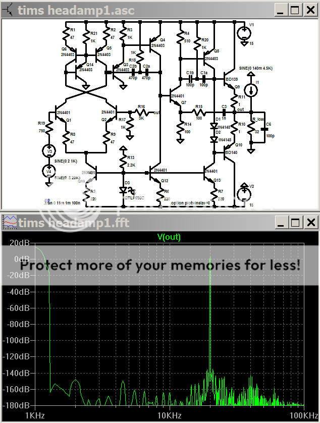
4x gain and 2.5x output - 10 V peak output amplitude and added output Z "test" disturbance current load - by balancing Zin to = fdbk Z 2nd harmonic of 1 KHz is kept to 147 dB down with a realistic Zsource
(it is left to the reader to determine why a low C schottky baker clamp is a good idea at Q8)
i kept the q# the same, it really is nice if you post the circuit file
You need to be aware that at these distortion levels your 0 source impedance is “cheating” – distortion from diff input Q ib, Zcb is significant when you add 1 K typical source impedance
Balancing source and feedback Z is the usual solution as you mention, I’ve also found that bootstrapped cascoding of the input is helpful in sim to reduce Zin matching requirement
Your heavy miller Cap compensation in main and output stage gives poor AC psrr from positive rail – maybe not a problem with batteries – but it can be fixed by moving gain from inside your local loops to global open loop gain with 2 pole compensation as I’m showing
Output swing can also be enhanced with the AC coupled feedback at the output stage – V gain in the output stage allows using more of the V headroom for mirror/vas/ccs cascodes and other “decoration”
I’ve only added 1 Q to balance up the current mirror and rearranged local feedback gains – in addition to adding the +4 closed loop gain feedback – even low Z cans need some gain
I’ve made no exploration of loop stability – I just halved the comp C values because they looked too big
4x gain and 2.5x output - 10 V peak output amplitude and added output Z "test" disturbance current load - by balancing Zin to = fdbk Z 2nd harmonic of 1 KHz is kept to 147 dB down with a realistic Zsource
(it is left to the reader to determine why a low C schottky baker clamp is a good idea at Q8)
i kept the q# the same, it really is nice if you post the circuit file
Attachments
Version 2.0!
JCX, I think I'll add that cascode you mentioned at a later date, for now I've merely fixed some stupid omissions on my part, namely R17.
I had previously tried the current mirror buffer that you suggested and found little improvment from it.
Gain in the CFB stage does not significantly help output swing as that is limited by Q8 and Q13 and not by Q4 and Q12. Though, as you said it might be of use when I add "decorations".
As you can see, it is now stable into a capacitive load, larger values of C1 allow much larger values for C2 (the capacative load).
JCX, I think I'll add that cascode you mentioned at a later date, for now I've merely fixed some stupid omissions on my part, namely R17.
I had previously tried the current mirror buffer that you suggested and found little improvment from it.
Gain in the CFB stage does not significantly help output swing as that is limited by Q8 and Q13 and not by Q4 and Q12. Though, as you said it might be of use when I add "decorations".
An externally hosted image should be here but it was not working when we last tested it.
As you can see, it is now stable into a capacitive load, larger values of C1 allow much larger values for C2 (the capacative load).
Attachments
I am not sure the output is CFB at all. To me, it is the good old EF output stage.
The amp has very well designed VAS and driver stage. Q7 and Q8 form the driver stage (and the way Q7's emitter is connected, it is extremely smart, and forms another current feedback loop). Q8 is the normal VAS, with a ccs load (Q13). Q9 and Q10 are the output transistors, in an EF topology.
Again, the way Q7 is used is very noval.
another way to look at it: anything to the right of Q7 is essentially a JLH front end/VAS + EF output stage. Something I had tried a while ago. it sounds good but suffers from poor output drift. But this particular design addresses that by incorporating a differential input stage.
If I were to redesign this thing, i would take a minimalist approach and take out the current mirror and CCSs.
but what we have is a very fine and noval design.
Hi tim_x,
Yes it is a standard EF output - but what you have here is nested feedback, hence the ultra-low THD. It works particularly well enclosing the output stage in 2 loops to bury it's non-linear vagaries with loading. But this is not so much the case with a 32R output buffered headphone amp and a trifle over the top.
Cheers,
Greg
- Status
- This old topic is closed. If you want to reopen this topic, contact a moderator using the "Report Post" button.
- Home
- Amplifiers
- Headphone Systems
- LTP+CFB Headphone Amp (spiced)