Hello all you wise people out there, I hope you can help me.
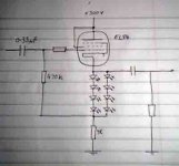
I've been tempted to buildthis circuit for a while now, but I've been inspired by SY's comments on LED biased output stages. Well this is what I have so far for the output stage, and I have a few questions. (please bear in mind I'm still fairly new to designing my own circuits)
How is the value of the grid input resistor derived, or if it is needed at all?
Same for the resistor between g2 and the anode on Helmut's design.
How is the value of the resistor accross the output terminals derived?
Thanks for any help,
Steve
Attachments
baggystevo82 said:someone out there must know? Or have I missed something stupidly blatantly obvious?
Steve
What bias voltage are you trying for on the cathode?
6.8v
or 4 x 1.7, that's another thing actually, my christmas effected head can't quite get round. As the voltage dropped accross the LED's isn't a product of ohms law, they just have a constant drop anyway (relatively), does that mean that the layout shown in that schematic will have the same drop but with double the current handling of 4 LED's in series on their own?
Cheers,
Steve
baggystevo82 said:does that mean that the layout shown in that schematic will have the same drop but with double the current handling of 4 LED's in series on their own?
Yep, 'think so. But I've got a 'Christmas-affected brain' too.
You're right about the LEDs- just think of them as a battery. Two strings in parallel double the current rating and halve the impedance. Figure that you'll end up with about 10 ohms- not bad!
Make sure that the 1K resistor has a nice, high current rating and you'll be good to go. A 470K value for the input resistor is probably OK, though with the bootstrapping inherent in your CF, you could drop that to 100K without harm. The grid stopper should be somewhere between 1K and 10K, with the body of the resistor as close to the tube pin as possible.
Make sure that the 1K resistor has a nice, high current rating and you'll be good to go. A 470K value for the input resistor is probably OK, though with the bootstrapping inherent in your CF, you could drop that to 100K without harm. The grid stopper should be somewhere between 1K and 10K, with the body of the resistor as close to the tube pin as possible.
Cheers SY. I've just done a bit of searching around and lots of people seem to recommend 1k grid stoppers on EL84's so I think I'll go with that. Any ideas why Helmut's uses only 100ohms here? I'm guessing I should include the 100ohm g2-plate stopper resistor too (is this the right term?), or should I leave it out and only include it if there's oscillation problems?
That resistor accross the output is still a problem for me though. Is it just there to keep the output tied to ground if no headphones are plugged in?
Oh sorry one more, if I drop the value of the grid leak resistor (I think that's its purpose here?) what value of R should I use to calculate the frequency response of the input coupling?
Cheers again!
Steve
baggystevo82 said:Any ideas why Helmut's uses only 100ohms here? I'm guessing I should include the 100ohm g2-plate stopper resistor too (is this the right term?), or should I leave it out and only include it if there's oscillation problems?
The resistor's size (when optimized) will vary from application to application. But really, it's pretty non-critical- if you use 4.7K, for example, you'll lose a tiny bit of bandwidth, which is critical only if you're a dolphin. But you'll be nearly guaranteed that the tube won't oscillate due to grid factors. Likewise, the g2 stopper- it may work fine without it, but 100 ohms in series will just eliminate the worry.
That resistor across the output is still a problem for me though. Is it just there to keep the output tied to ground if no headphones are plugged in?
Yes.
Oh sorry one more, if I drop the value of the grid leak resistor (I think that's its purpose here?) what value of R should I use to calculate the frequency response of the input coupling?
The grid leak is bootstrapped by the cathode resistor. So its effective value is multiplied by the feedback factor. What's the mu of a triode strapped EL84?
Cheap red LEDs have a lower impedance than the UV LEDs, even taking into account the need to series more red LEDs.
With a mu of (roughly) 20, you've got a feedback factor of 20 to get to unity gain. So the input resistor's value is multiplied by 20 to get the input impedance. A 100K resistor will make sure that grid current isn't a problem, and it will appear to the outside world like a 2M resistor. Use that value to calculate f3 from the input cap.
With a mu of (roughly) 20, you've got a feedback factor of 20 to get to unity gain. So the input resistor's value is multiplied by 20 to get the input impedance. A 100K resistor will make sure that grid current isn't a problem, and it will appear to the outside world like a 2M resistor. Use that value to calculate f3 from the input cap.
That sounds nice and simple ") Thanks.
Thanks.
Is there any way of calculating the maximum possible resistor accross the output (if this is desirable?) like some kind of time constant related thing to the output cap?. I guess the value of the output cap will be determined by the lowest impedence headphones likely to be attatched (probably around 36ohms).
I think the main thing to sort out now will be how to drive this. I have a pair of 6922 and 6n1p's on hand, though people say lots of good things about ecc99's which shouldn't be too hard to get hold of. Any thoughts?
Thanks for your time!
Steve
Thanks.Is there any way of calculating the maximum possible resistor accross the output (if this is desirable?) like some kind of time constant related thing to the output cap?. I guess the value of the output cap will be determined by the lowest impedence headphones likely to be attatched (probably around 36ohms).
I think the main thing to sort out now will be how to drive this. I have a pair of 6922 and 6n1p's on hand, though people say lots of good things about ecc99's which shouldn't be too hard to get hold of. Any thoughts?
Thanks for your time!
Steve
Oh, yeah, that's a way lower f3 than you'll ever need. 22nF will work fine. So would 10nF, for that matter. The limitation will certainly be in the output cap.
In the input spot, a nice foil/pp cap would do very well. Nothing fancy, a Wima FKP or something like that is as good as it gets in this usage. Output cap, I have no experience, but a motor run polyprop would be the first thing I'd be inclined to try.
In the input spot, a nice foil/pp cap would do very well. Nothing fancy, a Wima FKP or something like that is as good as it gets in this usage. Output cap, I have no experience, but a motor run polyprop would be the first thing I'd be inclined to try.
Yeh I found a thread or two about some 250v 330uF motor run caps that would be good, having trouble sourcing them at the moment, I think I'll just have to leave space for them in case some turn up.
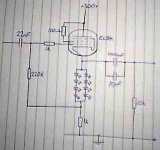
Well here's what I have so far then, now onto the driver stage
Well here's what I have so far then, now onto the driver stage
Attachments
- Status
- This old topic is closed. If you want to reopen this topic, contact a moderator using the "Report Post" button.
- Home
- Amplifiers
- Headphone Systems
- LED biased EL84 headphone amp