hi there......yes the sowter 8665 (I'd missed that one in the cat), interesting ratio combination, however the bogey comes with the massive 12:1 ratio with the lower o/p Z requirements.........the cathode follower would have to be cranked-up to get a suitable o/p level without introd excess thd.
Bear in mind that the parafeed series capacitor is a high value as;
1. To preserve the LF response down to the lowest freq under load.
2. Avoid series tank resonance with low uF series Cap. The series inductance of the parafeed transformer (dep on type) will be between 30-75 Henries; if a series cap of say 2uF is fitted, the effect will be a lift in the Q between 15-20Hz and the response with change with differing loads.
As I work with levels of 16dBu (or 5V o/p) I used a large 68uF film type with a 3:1 paratrans ratio for flat resp down to 15Hz.
These problems are unlikely to be found in normal use, unless the output is connected to a lower Z, i.e headphones.
The remainder is the cathode follower stage, mine draws 15mA for good o/p damping and no feedback.
rich
Hi there again,
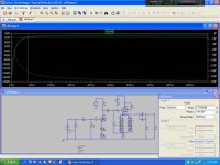
I've been hard at work at uni since Christmas and have a holiday coming up, so hoping to make some progress on this project soon. I've just been playing round with LTSpice for some coursework, and thought I may as well try this circuit out, and found that the interstage cap just before the EL84 was the weak point in frequency response. Changed the value of the input cap, not much change, changed the output cap, even down to only 100uF (with 250ohm headphones) still not much change, but putting the middle one up to 100nF made a huge difference. So now I have an input cap of 100nF still, middle cap of also 100nF, and have dropped the output cap to 220uF (from 1000uF). According to the sim this gives me a f-1dB point at around 9Hz for the whole amp. Do these numbers make sense? I wouldn't be so unconfident in my decisions, except that this is my own scratch(ish) designed amp, all my others have been kits or other peoples circuits.
Thanks for your help!
Steve
Attachments
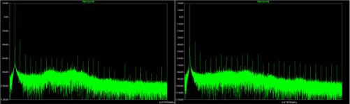
Done some more, deciding what load resistor to run on the 6N1P stage now. Here's the FFT for 10k on the left, and 15k on the right, both with a 1V p-p input.
10k has gain 22.6 and 1.5W dissipation
15k has gain 25.4 and 1W dissipation
Any thoughts on which might be best? At least in theory...
Cheers,
Steve
10k has gain 22.6 and 1.5W dissipation
15k has gain 25.4 and 1W dissipation
Any thoughts on which might be best? At least in theory...
Cheers,
Steve
Attachments
Hi again,
Sorry to keep on, but I can't work out what's happening here...
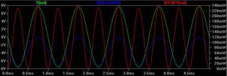
Ok, in the graph below, green is the voltage the headphones see, red is the power output through the headphones, and blue is the cathode to grid voltage.
I did have 4 pairs of LED's to bias at around 7-8V, in this sim I only have one pair, so shouldn't the grid be biased at -1.7V in this case? How has the grid managed to keep itself biased at around -4V? Confused!
Thanks for any help,
Steve
Sorry to keep on, but I can't work out what's happening here...
Ok, in the graph below, green is the voltage the headphones see, red is the power output through the headphones, and blue is the cathode to grid voltage.
I did have 4 pairs of LED's to bias at around 7-8V, in this sim I only have one pair, so shouldn't the grid be biased at -1.7V in this case? How has the grid managed to keep itself biased at around -4V? Confused!
Thanks for any help,
Steve
Attachments
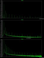
OK, still don't quite understand what's going on in my last post, but the circuit is now biased with 3 pairs of led's so the bias doesnt float around dependant on signal amplitude, and keeps it well away from grid current. Here's distortion figures for different power levels, into a 250ohm load, and the FFT's that the numbers were derived from...
1mW - 0.21% THD
10mW - 0.67% THD (0.02% if the 2nd harmonic is ignored") )
)
100mW - 2.65% THD
Hopefully this topology will have enough to power the headphones without distorting too much.
Cheers,
Steve....PS still looking for guidance or at least some comment that what I'm doing isn't completely wrong....
1mW - 0.21% THD
10mW - 0.67% THD (0.02% if the 2nd harmonic is ignored
)100mW - 2.65% THD
Hopefully this topology will have enough to power the headphones without distorting too much.
Cheers,
Steve....PS still looking for guidance or at least some comment that what I'm doing isn't completely wrong....
Attachments
Looking at the circuit.....I suspect some thd is coming from the output bootstrap, loading down the input impedance on to the output of first stage...Looking at the graphs........you assume signal+noise.....have you done one with only noise ? The amp configuration, OMV......I ‚d probably use a different tube than EL84 i.e use parallelled triode stages to get the impedance & thd down and headroom volts level up....there‘s been quite a few ideas on this forum site....I think you are getting alot of thd for the cost of an EL84.........way more than your standard hifi is producing... you are assuming true sine wave and not beat note distortion which can be way higher........... close environment headphone listening is very sensitive to oddies in the signal and circuit....hence headphones are for disconerning listening....(depends if you just like roudy and rave music without making the background noise out) but when someone else listens to your phones... you are to impress...
In the past, only my story.. I’ve had problems with tube headphone amps with over–circuit complication to obtain the extremely low noise requirement for quiet classical passages. So I’ve ventured to multi op amp designs..... Using my favorite headphones Sony MDR series 40 ohm Z, these are sensitive......and require amp signal/noise min –95dB ref 0dBu for no hiss audibility. There isn’t a single parafeed o/p without running into distortion at that volts level with low ouput impedance....Without getting in standard SE o/p stage complexity with tranny ...the thd would be lower but you would be looking at a large stepdown......and high primary signal swing.
The major drawback with cathode follower circuits is it can only drive down to certain loads....otherwise you will get asymettrical clipping on the neg signal side.
So what to do ?.... your rescue bet is to stay and stick with high Z phones and hear what you have made first.......but if you put low Z phones in, you will soon hear the disadvantages.
Bear in mind on the design level......the volt level on low impedance headphones can be quite normal especially when bass boost (or loudness control) is thrown in. 6V into 40 ohms is nar the 1 watt level and on some low end passages this level can be acheived without serious ear discomfort (these levels can be quite normal for steel band bass and studio re-mix) and depends on the coupling nature of the earsets.........this important bit.... some headphones models come with level limiters to avoid deafness litigation.
....Noise assessment levels..... these signal levels I’ve quoted are high, especially the real danger of using sine wave and many techno fans like high levels....some sounds are so continuous to resemble sine and square wave.... In the mid range you will become permanently stone deaf..
Another of my disclaimer warnings ..I accept no responsibility for this. But offerered in good faith...... There is a rough 2 yard-stick for critical headphone levels.......If two persons have to shout to be understood when standing 2 yards apart .....that is only one of them is wearing headphones........ rough guide.....
richj
Hi again Rich!
I'm fairly committed to using high Z phones with this design now. My housemate has some Senn HD650's that I can test with and make sure I like the circuit before splashing out on some high Z cans myself (though I doubt that high end). My main reasoning behind using el84 is that I already have a pair of Sovtek EL84M's hanging around not doing very much. Agreed though the performance of this circuit into 40ohm headphones would be pretty dismal by the looks of it. I did fancy the idea of going OTL for a headphone amp though, due the availability of high Z drivers.
As for the THD figures from the sim, I think they are only THD and not THD+N, unless it's randomly worked that out for me too. Hopefully I should be able to keep noise down with careful component selection and construction, all my amps to date have been whisper quiet.
Any chance you could elaborate on what you mean by the output bootstrap please? This is by no means my final design/layout and I would be grateful for any potential improvements. Also wouldn't 'beat note distortion' as you put it be equivelant to the amps transient capabilities? In which case I think this should be dictated by the upper bandwidth limit of the amp, as it's class A I don't think power supply should come into it quite so much? So long as it is fairly 'sturdy'?
As for the kind of music I listen to, probably best I list a few bands...
Incubus
Tool
A Perfect Circle
Sublime
Pink Floyd
The Who
Green Day
Rival Schools
The Specials
The Pixies
etc etc etc
and for noise level.... 1W through 96dB/mW phones??? I doubt I'd like that too much. Hopefully <10mW will be enough?
Cheers for all your help!
Steve
I'm fairly committed to using high Z phones with this design now. My housemate has some Senn HD650's that I can test with and make sure I like the circuit before splashing out on some high Z cans myself (though I doubt that high end
). My main reasoning behind using el84 is that I already have a pair of Sovtek EL84M's hanging around not doing very much. Agreed though the performance of this circuit into 40ohm headphones would be pretty dismal by the looks of it. I did fancy the idea of going OTL for a headphone amp though, due the availability of high Z drivers.As for the THD figures from the sim, I think they are only THD and not THD+N, unless it's randomly worked that out for me too. Hopefully I should be able to keep noise down with careful component selection and construction, all my amps to date have been whisper quiet.
Any chance you could elaborate on what you mean by the output bootstrap please? This is by no means my final design/layout and I would be grateful for any potential improvements. Also wouldn't 'beat note distortion' as you put it be equivelant to the amps transient capabilities? In which case I think this should be dictated by the upper bandwidth limit of the amp, as it's class A I don't think power supply should come into it quite so much? So long as it is fairly 'sturdy'?
As for the kind of music I listen to, probably best I list a few bands...
Incubus
Tool
A Perfect Circle
Sublime
Pink Floyd
The Who
Green Day
Rival Schools
The Specials
The Pixies
etc etc etc
and for noise level.... 1W through 96dB/mW phones???
I doubt I'd like that too much. Hopefully <10mW will be enough?Cheers for all your help!
Steve
baggystevo82 said:
Any chance you could elaborate on what you mean by the output bootstrap please? This is by no means my final design/layout and I would be grateful for any potential improvements. Also wouldn't 'beat note distortion' as you put it be equivelant to the amps transient capabilities? In which case I think this should be dictated by the upper bandwidth limit of the amp, as it's class A I don't think power supply should come into it quite so much? So long as it is fairly 'sturdy'?
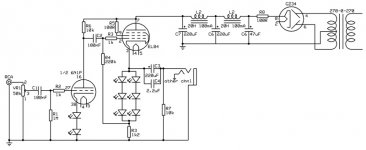
Output bootstap....actually I misviewed the cct diagram. feedback from o/pstage to input of input tube.........doesn't apply in your case as between stages is broken by vol control. Also anode load in first stage is nice and low, again ideal. lowering the input impedance.....not always desirable.
As class A....psu problems won't exist. Only that the cmr rejection probably won't be good make sure no noise comes from this.....however your B+ looks good.
As for music....mixed bag..I'm a steel fan ...Port au Prince ...Tabou Combo...impossible to replay the deep bass unless record player sits on a concrete slab (monument) and pickup weighted down with a cent bit. One of those recordings where the bass line can shaker the building and overload the RIAA eq....Yo er what I mean ? CD is cleaner and does help matters.
richj
richwalters said:
Also anode load in first stage is nice and low, again ideal.
Hehe, just been working on a slightly modified first stage with only one led biasing, and a 15k load. This reduces distortion of the first stage at 5v p-p output to around 0.03% THD, down from over 0.06% that it was in this part of the circuit earlier (with 2led's biasing and a 10k load). Is this right to do?
Cheers,
Steve
Back again!!! More rethinking going on....
I think I'll still stick with the LED biasing, but moving accross to transformer coupled output now I think...
Just a short question to start with though, as a triode, EL84 maximum plate voltage = 300v. Does this mean that I can use a higher b+ (like 450-500v) so long as the grid doesn't go negative enough to exceed this rating?
Cheers,
Steve
I've just find this page:
http://www.turneraudio.com.au/htmlwebpgs02/schemrevisedst70.htm
looking at the output stage cathode bias I've seen the zener diode string across each cathode RC network. Its purpose is to limit the rise of voltage in the cathode bypass caps when the amp works hard in class AB. Can this be worthwhile for standard cathode bias?
Mark
- Status
- This old topic is closed. If you want to reopen this topic, contact a moderator using the "Report Post" button.
- Home
- Amplifiers
- Headphone Systems
- LED biased EL84 headphone amp