here:
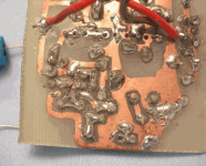
backside with my amateur circuit layout
done with a water resistent ink pen
and etched in my kitchen
circuit is extremely compact (about 20x20 mm for each amp)
short signal travel was my obsession those days long ago
(excuse the dirt and dust, didnt clean it before taking picture)
backside with my amateur circuit layout
done with a water resistent ink pen
and etched in my kitchen
circuit is extremely compact (about 20x20 mm for each amp)
short signal travel was my obsession those days long ago
(excuse the dirt and dust, didnt clean it before taking picture)
Attachments
Re: Schematic please Line up....post it here...headphones...best wide world headphone
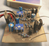
Use magnifying glass and get resistor values and details.
But what i have estimated:
T1T2 input differential has got ~0.450 - 0.500 mA each.
Because PNP BD140 in second stage has got Emitter to +12Volt
and between B-E a resistor 1k5. (0.650 / 1.5 = 0.43 mA)
Second stage is (from 9.7 Volt at output BD139 base)
two resistors 820 + 150 Ohm.
Makes 10 mA in BD140.
And so, total gain is (820+150)/150 = 6.4
Output has got ~9.0 Volt at BD139 emitter,
and from there goes 3 resistors in series:
3 x 39 Ohm.
You can see them next to output transistor, with the colours for 39 Ohm.
Makes output stage be biased 9/108 = 83 mA.
Of course can be adjusted a bit with potentiometer that bias the input.
The resistor from both input transistors Emitters (long tail resistor)
is 820 Ohm.
Across that resistor should be something like 0.9 Volt
so gives those 2 input transistors share:
1.1 mA
As mentioned, T1, has got like 0.43 mA
leaves like .0.67 for T2
(Ideally they should carry exactly 50%)
Hope you can build this circuit now.
I know you can.
You are NOT what we could call UN-Experienced DiyAudio experimenter")
Carlos.
---------
PS.
I'd like to build an improved version of this nice sounding headphone amp.
I remember so well that day:
I cried tears, of joy, when I had buillt it
and listened to a fantastic sound quality of it ....
... my first real diy audio creation!
From circuit, to layout and build!
Have to make some backengineering.destroyer X said:Amplifier(s).
Please..... post it here Line up.
Very nice board, interesting circuit...let us know it!
regards,
Carlos
Use magnifying glass and get resistor values and details.
But what i have estimated:
T1T2 input differential has got ~0.450 - 0.500 mA each.
Because PNP BD140 in second stage has got Emitter to +12Volt
and between B-E a resistor 1k5. (0.650 / 1.5 = 0.43 mA)
Second stage is (from 9.7 Volt at output BD139 base)
two resistors 820 + 150 Ohm.
Makes 10 mA in BD140.
And so, total gain is (820+150)/150 = 6.4
Output has got ~9.0 Volt at BD139 emitter,
and from there goes 3 resistors in series:
3 x 39 Ohm.
You can see them next to output transistor, with the colours for 39 Ohm.
Makes output stage be biased 9/108 = 83 mA.
Of course can be adjusted a bit with potentiometer that bias the input.
The resistor from both input transistors Emitters (long tail resistor)
is 820 Ohm.
Across that resistor should be something like 0.9 Volt
so gives those 2 input transistors share:
1.1 mA
As mentioned, T1, has got like 0.43 mA
leaves like .0.67 for T2
(Ideally they should carry exactly 50%)
Hope you can build this circuit now.
I know you can.
You are NOT what we could call UN-Experienced DiyAudio experimenter
Carlos.
---------
PS.
I'd like to build an improved version of this nice sounding headphone amp.
I remember so well that day:
I cried tears, of joy, when I had buillt it
and listened to a fantastic sound quality of it ....
... my first real diy audio creation!
From circuit, to layout and build!
Class A headphone amp
Hello to Carlos!
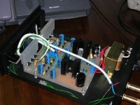
Something I built sometime ago. It is a class A with FET input and output. Sounds very good with very low deep bass and wide sounstage. Highs are clean and not boring. Well it is not from me but a good friend from Norway designed it and I built it.
You should try it and realise the speed and slam it can give.
Cheers.
Good things are not cheap when cheap things are not good.
Hello to Carlos!
Something I built sometime ago. It is a class A with FET input and output. Sounds very good with very low deep bass and wide sounstage. Highs are clean and not boring. Well it is not from me but a good friend from Norway designed it and I built it.
You should try it and realise the speed and slam it can give.
Cheers.
Good things are not cheap when cheap things are not good.
Attachments
Please RSK, publish the schematic for us
Personally i have some problems with FETs...i have not many different units, and i have only two or three units in pairs.
But despite my problems, the schematic is interesting to many forum guys that may use it immediattelly.
If you want to use this space, please, the house is ours...our forum!
regards,
Carlos
lineup headamp schematic
hi there
this is same basic schematic as my headamp
See description in my post earlier in this thread:
http://www.diyaudio.com/forums/showthread.php?postid=995718#post995718
and the pictures in the follwing posts.
I will post an instrcution for building this amp ( 67 steps numbered 01-67 ),
as several of you may need a lot of assistance and help,
maybe next week.
Until then, here is a SCRATCH for those that can figure out the details
for themselves.
Here you are.
I dont expect any thanks or such stuff.
(No use in these forums - will let you down only)
lineup
.............................
*note:
This is an 'improved version'.
Because I have learnt 1 or 2 things these past 10 years, since built this litte amp.
Most of it in www.diyaudio.com - in fact!
hi there
this is same basic schematic as my headamp
See description in my post earlier in this thread:
http://www.diyaudio.com/forums/showthread.php?postid=995718#post995718
and the pictures in the follwing posts.
I will post an instrcution for building this amp ( 67 steps numbered 01-67
),as several of you may need a lot of assistance and help,
maybe next week.
Until then, here is a SCRATCH for those that can figure out the details
for themselves.
Here you are.
I dont expect any thanks or such stuff.
(No use in these forums - will let you down only)
lineup
.............................
*note:
This is an 'improved version'.
Because I have learnt 1 or 2 things these past 10 years, since built this litte amp.
Most of it in www.diyaudio.com - in fact!
Attachments
Yo lineup, I have to say I saw where you were comming from... I'm just old enough to stay out of other people's misundestandings by now....
Anyhow I would like to report back on my further headphone amp experiments... spend all of yesterday and most of today building Rod Elliot's ... OMW something is somekeing......
Hahah ok note to self: do not use NiiCd bateries with normal ones again.... it ******* melted and started smokeing while playing on, the whole cover is melted away...
Erm lets just just check, ja still working.
.... all of yesterday and most of today building Rod Elliot's P109
All I could find on Saturday morning was 3 LM358 opamps and even using those I am impressed off my chair... not with the sound per se- it would be hard with the cheap chips- but with the crossfeed.... IT IS A MOST MAGNIFICENT THING. Its a very good circuit though... the noise floor is below the natural his in your ears....
I would like to see a discrete circuit where we could add this function to.
Anyhow I would like to report back on my further headphone amp experiments... spend all of yesterday and most of today building Rod Elliot's ... OMW something is somekeing......
Hahah ok note to self: do not use NiiCd bateries with normal ones again.... it ******* melted and started smokeing while playing on, the whole cover is melted away...
Erm lets just just check, ja still working.
.... all of yesterday and most of today building Rod Elliot's P109
An externally hosted image should be here but it was not working when we last tested it.
All I could find on Saturday morning was 3 LM358 opamps and even using those I am impressed off my chair... not with the sound per se- it would be hard with the cheap chips- but with the crossfeed.... IT IS A MOST MAGNIFICENT THING. Its a very good circuit though... the noise floor is below the natural his in your ears....
I would like to see a discrete circuit where we could add this function to.
You can add a crossfeed in front of any amp with highish input impedance. See : http://tangentsoft.net/audio/mlxfeed.html I personnaly don't like crossfeed, nor the linkwitz, nor Jan Meier's.
That project is probably decent sounding, it's the kind of things I've been starting DIYing with. You can do a lot better.
For low impedance cans, see that one for example : http://headwize.com/projects/showfile.php?file=gilmore3_prj.htm (you can simplify the PS a bit if you want).
That project is probably decent sounding, it's the kind of things I've been starting DIYing with. You can do a lot better.
For low impedance cans, see that one for example : http://headwize.com/projects/showfile.php?file=gilmore3_prj.htm (you can simplify the PS a bit if you want).
Nordic said:Thanks for the links.. of course my big goal is also partialy portability... current circuit is about 2 x 2 inch fiting in a case of that with, twice the length and about 3/4" height.....
As told, my circuit is very compact
for 2 channels stereo driving for example 2x32 Ohm
including LIM317 regulator, it is only 47.5 x 62.5 mm.
See picture in Post # 80
http://www.diyaudio.com/forums/showthread.php?postid=995720#post995720
You would need a small trafo, though.
Minimum: 3.5 VA 1x12 Volt
Recommended (see my schematic) : ~5.0 VA 15 Volt
I am thinking of building Lineup HeadPhAmp Mk.2
and do it the hardwire way without PCB board!
That would be really something
... when already the old circuit gave me tears of joy
when listening.
You might like this : http://www.meier-audio.homepage.t-online.de/headamp.htm Still wall powered though.Nordic said:Thanks for the links.. of course my big goal is also partialy portability... current circuit is about 2 x 2 inch fiting in a case of that with, twice the length and about 3/4" height..... (10x5x2 cm)
This schematic, that is not the developed one, is already interesting
And i see that bias can be reduced to intall headphone coil in series..... under 60 miliwatts may work fine without melt the cartridge..... i use try this one someday.
I am imagining how good may be the complete version...hummmm, it may be very good...hummmmm.
regards,
Carlos
And i see that bias can be reduced to intall headphone coil in series..... under 60 miliwatts may work fine without melt the cartridge..... i use try this one someday.
I am imagining how good may be the complete version...hummmm, it may be very good...hummmmm.
regards,
Carlos
Attachments
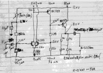
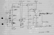
that is my new version
notice I changed BD140
and use better BC557 PNP
I dont know why I used BD140, even if result was good
there is no need for it
maybe, the simple fact I had no TO-92 PNP, like BC557, at home this day
and took what PNP I had ....
About resistors in input:
from top:
100k trimmer (can be replaced with ~68k resistor)
150k
47k
and below T1-T2 input pair:
180 Ohm +
180 Ohm
(no big catastrof replace with one 330 Ohm or 390 Ohm)
about transistors:
I would use ( in schematic )
t1-t2 = BC550C ( BC547 )
t3 PNP = BC560C ( BC557 )
t4 NPN = BD139 ( BD139 )
One trafo ~4-5 VA 12-15 Volt
would supply both 2 channels. ( 100mA per channel )
For regulator use something like this:
7812 12V 0.5A ( or 1A ) 3-pin regulator
or
LM317 TO-220 case
12 Volt DC regulators are not difficult to find.
Follow instructions for those regulators when setup.
As this is a
Fully discrete Single End TRUE Class A amplifier
trafo should be able to feed regulator input
with a voltage like 15 Volt or more
at the Class A constant current of 100+100 mA = 0.2A
good luck
if anyone build it - you wont be dissapointed with sound!
I can promise
if your headphones are of same good quality, as my amplifier
/lineup
Very good informs, and a good will information for us..this is very kind
I think i will construct it, as soon as i have more acid to produce boards...or maybe some stripped copper board.
The circuit is very interesting... and now complete with informs and graphics, can be used by everyone around the world..this is something great that our forum provide to anyone.
But if someone have other ideas, please, post the ideas here, as we are searching for multiple ideas, and each one of us will decide the one adequated to construction, based on each one's needs and desires.
Thank you.
regards,
Carlos

- Status
- This old topic is closed. If you want to reopen this topic, contact a moderator using the "Report Post" button.
- Home
- Amplifiers
- Headphone Systems
- New best wide world headphone amplifier