I don't know much about SMD. I cannot solder those chips with no pin.
Watch some YouTube howto videos and you will get it in no time. Get good ($20 stainless steel Swiss-made tweezers, flip up binocular magnifiers, solder paste in syringe, liquid flux, a skillet, and a hot plate). Hot air gun works well too but $40 and useful when you are serious.
Videos made by Sparkfun on SMD soldering are useful.
For conventional soldering iron - Just solder one end first, hold part down with tweezer pressure and solder other end. A 1mm round or chisel tip works well.
I used hakko 936.
I don't have tweezers so I used a small screw driver with cotton to hold resistors and x7r caps. I really suck in soldering.
Thanks letting me know where to start.
As for the opa1688 I used soic8 to pdip socket. Thanks to that lady who repair smartphones in a shop who soldered opa1688 on pdip socket.
Add 0.1uF film and 4.7R Zobel to absorb any RF oscillation.
While this sledgehammer may absorb RF oscillation, it will also surely cause instability with most amplifiers. Not many that I know of can drive 0.1µF and remain stable, especially with only 4.7Ω of series resistance.
Isn't the point to have a stable amplifier, and not just flatten the oscillation out of the output jack?
The 0.1uF and 4R7 is usually placed in a Class AB amp with negative feedback to absorb oscillations that may arise from certain loads plugged into the amp. Certainly it is not the purpose to absorb on-going oscillations. The amp should be stable on its own. If you have this in place, it can save an amp from self destruct if an unstable load is plugged into it.
On the OPA1688, it does not present a problem, the amp as designed in the last schematic is stable and works very well as it has now been tested. The output coupling caps are 1100uF effective capacitance, and is driven just fine.
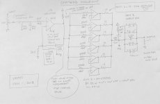
OPA1688 HPA with AC-coupled output
The amp was built and tested and sounds excellent. I skipped the input coupling cap since the output is already AC coupled. Recall the reason for AC coupling the output is to protect the headphone from DC errors in case the power supply rail becomes asymmetric. I also deleted the feedback shunt cap - no need since the opamp maintains about 1mV DC offset in DC coupled output mode.
I have tested it with maybe 10 tracks. It sounds excellent. Surprisingly very powerful bass. Very good clarity and overall great neutral sound quality. I can see why this opamp is used as the output stage for a lot of nice DACs.
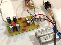
Here is the HPA connected to my Focusrite DAC and OB-1 headphones:

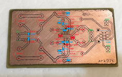
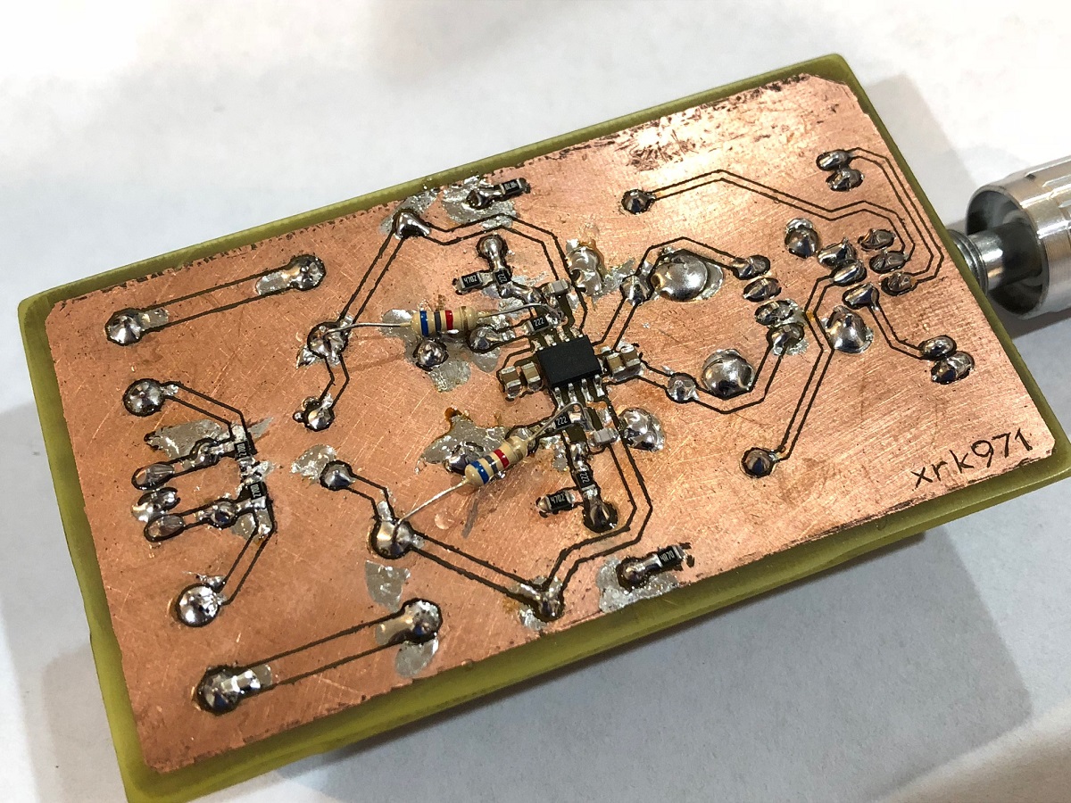
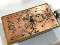
This is the underside showing the SMT components. It's a bit messy as I did some tests by pulling out the caps and running DC coupled all the way through (it works well this way too). I am using a carbon film axial feedback resistor and in conjunction with 2k2 gives 4.1x gain:
The amp was built and tested and sounds excellent. I skipped the input coupling cap since the output is already AC coupled. Recall the reason for AC coupling the output is to protect the headphone from DC errors in case the power supply rail becomes asymmetric. I also deleted the feedback shunt cap - no need since the opamp maintains about 1mV DC offset in DC coupled output mode.
I have tested it with maybe 10 tracks. It sounds excellent. Surprisingly very powerful bass. Very good clarity and overall great neutral sound quality. I can see why this opamp is used as the output stage for a lot of nice DACs.
Here is the HPA connected to my Focusrite DAC and OB-1 headphones:
This is the underside showing the SMT components. It's a bit messy as I did some tests by pulling out the caps and running DC coupled all the way through (it works well this way too). I am using a carbon film axial feedback resistor and in conjunction with 2k2 gives 4.1x gain:
Attachments
Monte McGuire is right, the zobel values aren't adequate for the opa1688. If you do a quick sim, you'll see that they create a bad peak a bit under 1Mhz. If you want a zobel, 47R+100n would be more adequate.
The 47pF feedback cap is oversized too, considering the gain and feedback resistors values. But that's less of a concern.
The 47pF feedback cap is oversized too, considering the gain and feedback resistors values. But that's less of a concern.
The 47pF value is the factory spec sheet recommended circuit. It’s also the one used by Agdr in his Super Cmoy. I have 36pF, 33pF, and 15pF NP0 to try. Will need to put it on oscope to check. Btw, I ran it in all DC coupled front to back and offset was 1mV per factory spec. The output coupler caps are here as simple way to protect for the what-if scenario of 1 battery clip coming loose first, as a huge portion of the Super Cmoy and even the O2 power supply systems are simply there to protect the headphones in the event of a power rail imbalance. A lot of complexity solved by a few caps. My qualitative sound quality listening session showed no discernible difference with output caps in place.
I can change out the Zobel resistors easily - they are at the edge of the board. Actually with a hot air gun anything can be changed easily.
The connectors are 2.54mm pitch JST style male PCB mount and female crimped shells. You can buy them ready made as battery harnesses for small RC cars or quadcopters. Or just buy them bare and crimp yourself. You need a good crimper tool to make effective crimped joints as too unreliable and time consuming to make by hand.
Assorted JST connectors:
2.54mm JST Connector Kit - RobotShop
Or here:
60 Sets JST xH 2.54mm 2 3 4pin Male and Female Housing Connector With Crimps | eBay
Great crimper tool:
Iwiss XH2.0mm XH2.54mm XH3.96mm Dupont D-Sub Terminals JST Pin Crimper SN-01BM Crimping Tools for Crimper Plier for AWG 28-20 (0.08-0.5mm2) Iwiss XH2.0mm XH2.54mm XH3.96mm Dupont D-Sub Terminals JST Pin Crimper SN-01BM Crimping Tools for Crimper Plier for AWG 28-20 (0.08-0.5mm2): Amazon.com: Industrial & Scientific
A cool (and still simple) variant of the project would be to make a quad parallel version in order to drive a maximum of 300mA into a 50ohm load. Would probably require a true 2sided board made by a factory. The outputs of four unity gain OPA1688 operation as buffers could be summed with four x 1R load balancing resistors with feedback taken from summed output to a master voltage gain opamp. Could use a 5th OPA1688 for that if even an LME49720.
I think that’s good for 500mW into 50ohms or thereabouts.
Last edited:
Of course, but 47pf is only valid in the context of that recommended circuit values. John Caldwell from TI kindly gave us the reasoning behind it here : http://www.ti.com/lit/ug/tiduaw1/tiduaw1.pdf (see pages 9-11). agdr has resistors values much closer to the datasheet.The 47pF value is the factory spec sheet recommended circuit. It’s also the one used by Agdr in his Super Cmoy. I have 36pF, 33pF, and 15pF NP0 to try. Will need to put it on oscope to check.
Without the zobel, best value would be somewhere around 8.2pF. But the zobel complicates things; you might want to try 22pF with a 47R+100n zobel.
@dibya: 100nF or 0.1uF
@00940: the problem with 47R is that it drops the Zobel low pass corner frequency from 330kHz to 33kHz. The psychoacoustic spatial cues of hearing use phase info embedded in audio at up to 300kHz. This is where stereo imaging and spatiality reside. The frequency cutoff of human hearing is circa 20kHz, but subconscious phase resolution at microsecond scale is what gives us sound stage and spatial info. I fear the Zobel with 47R is going to distort that phase info.
@00940: the problem with 47R is that it drops the Zobel low pass corner frequency from 330kHz to 33kHz. The psychoacoustic spatial cues of hearing use phase info embedded in audio at up to 300kHz. This is where stereo imaging and spatiality reside. The frequency cutoff of human hearing is circa 20kHz, but subconscious phase resolution at microsecond scale is what gives us sound stage and spatial info. I fear the Zobel with 47R is going to distort that phase info.
We hear frequency between 20Hz and 20kHz but the spatial info is contained in microsecond phase shifts, which means it is up to 300kHz or more where phase resides that impacts sound stage. This is why some amps with lower feedback or zero global feedback have better imaging and spatiality. Their phase is flat up to several MHz.
@00940: the problem with 47R is that it drops the Zobel low pass corner frequency from 330kHz to 33kHz. The psychoacoustic spatial cues of hearing use phase info embedded in audio at up to 300kHz. This is where stereo imaging and spatiality reside. The frequency cutoff of human hearing is circa 20kHz, but subconscious phase resolution at microsecond scale is what gives us sound stage and spatial info. I fear the Zobel with 47R is going to distort that phase info.
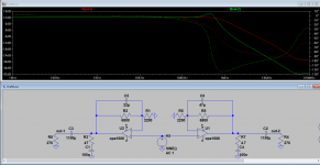
I'm not sure I'm buying into that whole flat phase to 300Khz theory but still : the 4.7r zobel messes up everything so bad that it doesn't matter what is its corner frequency. With 4.7r, you need a big feedback compensation cap to counteract the peak created by the zobel (I wouldn't use compensation caps under 47pf as long as you have that zobel btw, phase margin goes down the drain). The 47pF cap combined with the 4.7r+100n zobel is starting to roll off before a combination of 22pF comp cap with 47r+100n zobel. See the attached sim.
To give some perspective: without zobel and with a 8.2pf comp cap, your gain margin is 74°, with 47r+100n and a 22pf cap, 95°. And with 4.7+100n and 47pf.... 37°. All calculations made with the simulated load suggested by John Caldwell and the model from TI under ltspice (using the Tian probe).
Attachments
I'm not sure I'm buying into that whole flat phase to 300Khz theory but still : the 4.7r zobel messes up everything so bad that it doesn't matter what is its corner frequency. With 4.7r, you need a big feedback compensation cap to counteract the peak created by the zobel (I wouldn't use compensation caps under 47pf as long as you have that zobel btw, phase margin goes down the drain). The 47pF cap combined with the 4.7r+100n zobel is starting to roll off before a combination of 22pF comp cap with 47r+100n zobel. See the attached sim.
To give some perspective: without zobel and with a 8.2pf comp cap, your gain margin is 74°, with 47r+100n and a 22pf cap, 95°. And with 4.7+100n and 47pf.... 37°. All calculations made with the simulated load suggested by John Caldwell and the model from TI under ltspice (using the Tian probe).
Thanks for doing the sim. Can you share the LTspice .asc file? Or show me where to get the 1688 model. I could also use a LME49710/20 model.
Thanks,
X
OPA1688 model: http://www.ti.com/lit/zip/sbom950
LME49710 model: http://www.ti.com/lit/zip/snam001
The LM4562 will also work, and might be a different model, but somehow, I decided the LME49710 was a 'better' model and have been using it for a while.
LME49710 model: http://www.ti.com/lit/zip/snam001
The LM4562 will also work, and might be a different model, but somehow, I decided the LME49710 was a 'better' model and have been using it for a while.
- Status
- This old topic is closed. If you want to reopen this topic, contact a moderator using the "Report Post" button.
- Home
- Amplifiers
- Headphone Systems
- best op amp for C'moy amp