Amp case
Struck on a different way of saving on a case. To ship the case (listed above) to SA is another $46 added on to the price.
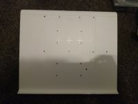
I have some old equipment (Onkyo tuner/amp with Tape, CD and Equaliser) that can be stripped of the innards, and a nice wooden faceplate can be made and fitted. The CD case is roughly 8.5" wide x 10" deep x 2" high. I can add a few ventilation holes to the top cover (respray,) add IEC power socket, RCAs et al to the back panel and voila! Probably put a bit of dampening onto the cover and base, and use small sorbothane feet. Much cheaper and fun to do. Shall post a picture when finally done. Still waiting for the PCB, but SA C&E and postal service on go-slow/strike.
Thanks to XRK and Co. for their hard work and dedication. Kevin
Struck on a different way of saving on a case. To ship the case (listed above) to SA is another $46 added on to the price.
I have some old equipment (Onkyo tuner/amp with Tape, CD and Equaliser) that can be stripped of the innards, and a nice wooden faceplate can be made and fitted. The CD case is roughly 8.5" wide x 10" deep x 2" high. I can add a few ventilation holes to the top cover (respray,) add IEC power socket, RCAs et al to the back panel and voila! Probably put a bit of dampening onto the cover and base, and use small sorbothane feet. Much cheaper and fun to do. Shall post a picture when finally done. Still waiting for the PCB, but SA C&E and postal service on go-slow/strike.
Thanks to XRK and Co. for their hard work and dedication. Kevin
I thought I'd have a go at matching some BF862s (will come in handy for the Simple amp that's up next.)
I'm using an SOT23 adapter and holding the FET on with a clothes peg.
I'm measuring Vgs of -0.55 and Idss of 42ma from the first two devices I tested. Idss seems way out of spec according to the datasheet.
Any suggestions as to where I'm going wrong would be appreciated.
I'm using a JFET matcher from Stompville, which seemed fine measuring some 2SK117s I had left over from some Reflektor-D builds.
The way to match them is in-situ using the amp PCB with resistor network in place and same operating Vcc. Put voltage probes across 1k1 resistor, place BF862 (device under test) across pads and use eraser on end of pencil to apply gentle pressure to pads. It will take about 15 seconds to thermally stabilize and measure that voltage. It will be in the 3.5v to 4.5v range and this is the operating bias current at the operating voltages. So approximately 3mA to 4.5mA bias current across the JFET. Put JFEt on sheet of paper and write voltage next to it. Keep doing this and then visually pair up matches (depends on threshold). A 2% match is perfectly fine but if you want you can get better than 0.5% match on maybe 2 to 3 pairs out of 100, and maybe 7 pairs within 1%, and more within 2%. Some will be total outliers. Some will be hotter than others and run 7mA even. Use for projects calling for higher Idss.
42mA is an awfully high number (you could use it as a power JFET to directly power a headphone almost as a source follower). I wonder if that may have to do with voltages. JFETs conduct fully at zero gate voltage. This amp doesn’t operate at zero gaye voltage - there is feedback from resistor network. So operating bias is circa 3mA to 5mA. That’s where it should be matched - at the same non-zero gate voltage applied.
42mA is an awfully high number (you could use it as a power JFET to directly power a headphone almost as a source follower). I wonder if that may have to do with voltages. JFETs conduct fully at zero gate voltage. This amp doesn’t operate at zero gaye voltage - there is feedback from resistor network. So operating bias is circa 3mA to 5mA. That’s where it should be matched - at the same non-zero gate voltage applied.
Last edited:
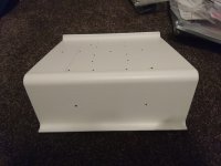
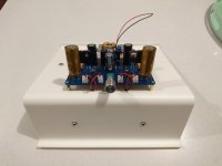
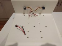
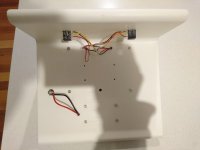
Sunday afternoon fiddling. Got the amplifier and boost mounted onto the ikea tablet stand haha. it was actually pretty thick so had to countersink the holes for the sockets, messed one of them up but overall quite happy. Added extra set of holes for the boost under the DCA board but decided not to use it.
I quite like this mounting method, will probably continue with it for future amps")
I quite like this mounting method, will probably continue with it for future amps
Attachments
I quite like this mounting method, will probably continue with it for future amps
YOB - Very innovative, fast and cheap. I have done all my diy amps (5 to date and busy with the Aksa Lender preamp now) using perspex and sometimes angled aluminium. All from off-cut materials that I get for free mostly. One word of advice - cover your naked amp when not used. In the space of 2 years my first headamp has gathered so much dust and it is now difficult to clean it. It still works fine!
I actually want to make a similar stand for my cell phone using perspex, since I often use my phone to stream music to my headamp.
The way to match them is in-situ using the amp PCB with resistor network in place and same operating Vcc.
Thanks X. Would matching them on the DCA be OK for matching purposes on the forthcoming Simple?
Thanks X. Would matching them on the DCA be OK for matching purposes on the forthcoming Simple?
Yes, that works and is what I did with excellent results. One of my Simple amps maintains 0mV DC offset on one channel- no pots, no servo opamps. The other channel is 3mV, and yet another pair is 1mV and 4mV. The accuracy of your 180R resistors is also important. Use 1% and even better, 0.1% metal thin film. I am actually using 220R for 20dB gain.
No, just V1 and V4 in schematic below. You are referring to the TimS HPA right? We should keep questions for that amp in that thread to avoid confusion.
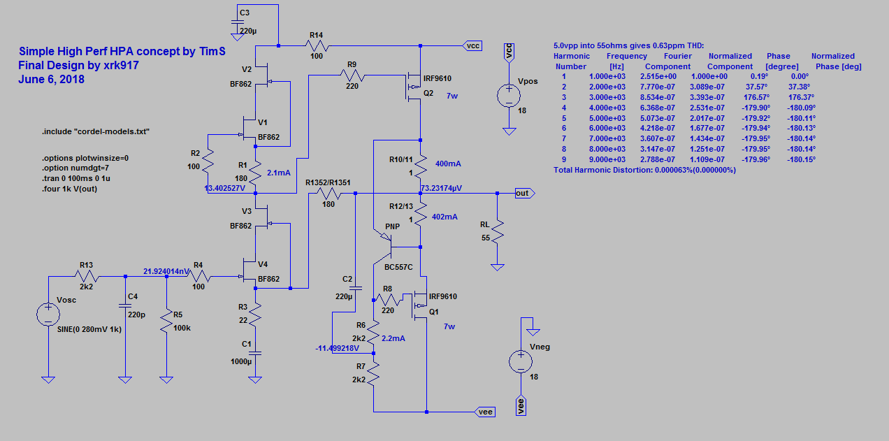
If you also matched V2 and V3 to each other, or would probably improve it some more. Although I have only matched V1 and V4 and used random ones on 2 and 3 and it works fine.
If you also matched V2 and V3 to each other, or would probably improve it some more. Although I have only matched V1 and V4 and used random ones on 2 and 3 and it works fine.
Last edited:

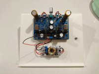
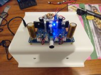
Only got it finished today. really pleased, sounds great with loads of power, definitely a good match for planars.
I had to use 1.5k for R106 to get ~10v, with 910r it was very high at 13V.
with sensitive headphones there is some low hiss, not sure if this is normal or if noise is being picked up somewhere.
I had to use 1.5k for R106 to get ~10v, with 910r it was very high at 13V.
with sensitive headphones there is some low hiss, not sure if this is normal or if noise is being picked up somewhere.
Only got it finished today. really pleased, sounds great with loads of power, definitely a good match for planars.
I had to use 1.5k for R106 to get ~10v, with 910r it was very high at 13V.
with sensitive headphones there is some low hiss, not sure if this is normal or if noise is being picked up somewhere.
Congrats!
Good that you got it dialed in at 10v mid point. I have never had to go to 1.5k before so it depends on JFETs I guess.
This amp should have no hiss. To check if hiss is inherent in amp or leading from the source, unplug the JST input jack or short the inputs without source connected. It should be silent. Plug in your source and see if that’s the hiss generator.
Just noticing the voltage drifts back to 13V even with 1.5K.
There is buzzing with no input connected. Shorting the left channel stops the buzzing but shorting the right channel causes a loud pop/crackle, I checked over the PCB connections and its all good, could this be a faulty transistor?
also the right channel power resistors and mosfet are a fair bit hotter than the left
Last edited:
- Home
- Group Buys
- xrk971 Desktop Class A (DCA) Headphone Amp