The crux of this trick is J4 and R73 setting an Id where J4's gate voltage V1a (on drawing below) is equal to the voltage at V2a, since V1a and V2a are effectively connected.
Since J3 is matched to J4 and R73 is equal to R78, and the Id is the same through both JFETs then the voltage at V2b is equal to the J3's V1b gate voltage.
This all sounds great except for one thing the Id for any Vgs varies with Vds, especially with low transconductance JFETs. This is where the cascode comes in, it keeps the JFET's Vds the same so the offset doesn't change with the supply voltage.
If you are seeing an offset then one of 3 things:
R73 is not equal R78
or J3 is not matched to J4
or R79 is connected directly to GND
If R79 is connected directly to GND (ie no C11) then the current through R78 is not equal to the current through R73. R73 should approximatly be equal to R79 in parallel with R78 with some 'trimming'. In this case the parts matching is also less critical.
Cheers
Tim
Thanks, TimS,
I had a wiring error which once fixed all works now. It’s a very elegant circuit and the sims look very good. I might build this for fun with a hand etched PCB and all SMT parts (except for MOSFETs and source resistors). Even though it has 7 parts, the little SOT23’s are tiny and cheap and side by side so complexity it more like a 5 active amp still.
Cheers,
X
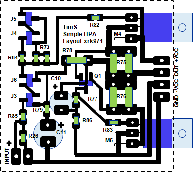
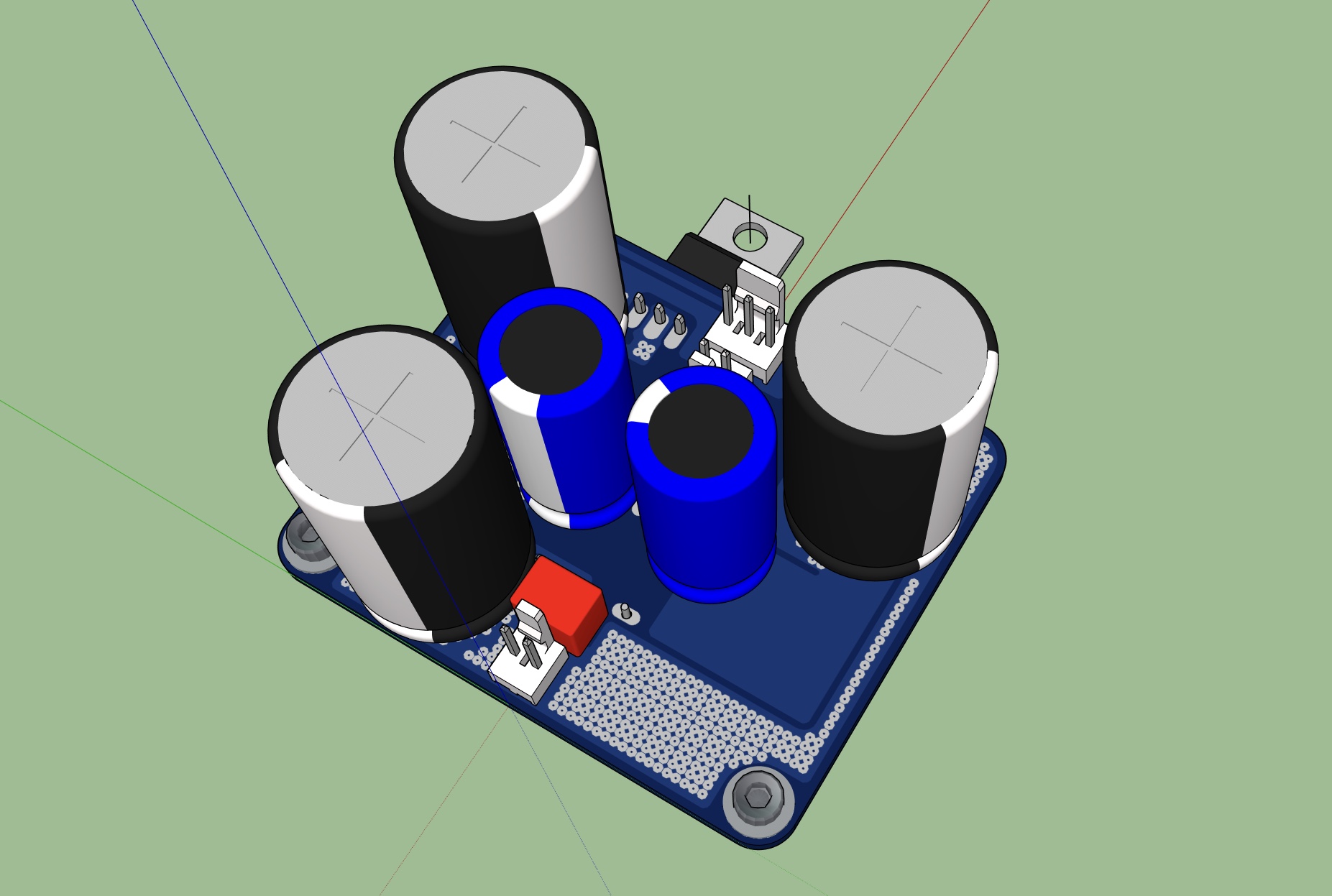
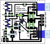
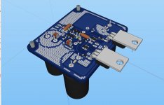
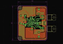
Here is a hand made layout I that I came up with to play around with while a pro layout is being finalized by JPS64, you can see what that looks like as well. On the final layout, we added an input RFI filter and some smoothing caps for the rails as well as a smoothing cap and RC de-coupler for the input stage to increase PSRR.


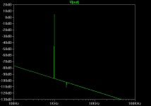
The sims look very promising indeed, here is 5vpp into 55ohms with 180mA bias current:
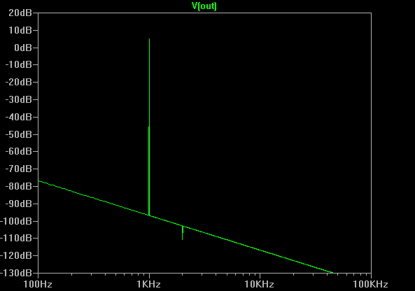
Here is corresponding distortion levels in numbers:
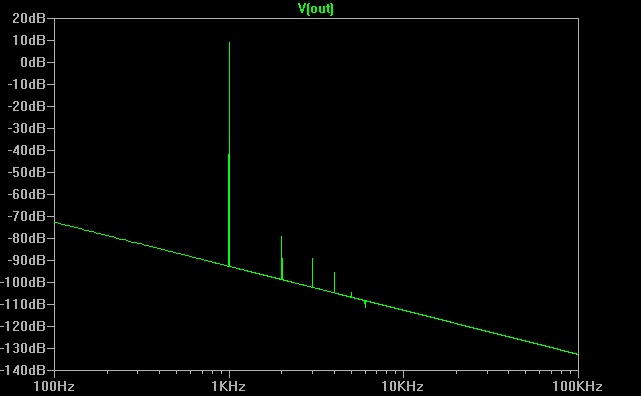
Here is 8vpp into 8ohms (1 watt into a speaker):
Here is corresponding distortion levels in numbers:
The above sims are with the plentiful and cheap BF862's and standard IRF9610.
I will test this out once I get the boards made. If there is interest, I will organize a GB (TimS has approved).
The sims look very promising indeed, here is 5vpp into 55ohms with 180mA bias current:
Here is corresponding distortion levels in numbers:
Here is 5vpp into 55ohms with 180mA bias
Harmonic Frequency Fourier Normalized Phase Normalized
Number [Hz] Component Component [degree] Phase [deg]
1 1.000e+03 2.525e+00 1.000e+00 0.16° 0.00°
2 2.000e+03 3.149e-06 1.247e-06 9.66° 9.50°
3 3.000e+03 2.117e-06 8.383e-07 169.65° 169.49°
4 4.000e+03 1.581e-06 6.263e-07 -179.94° -180.10°
5 5.000e+03 1.244e-06 4.925e-07 -179.88° -180.04°
6 6.000e+03 1.035e-06 4.101e-07 -179.97° -180.13°
7 7.000e+03 8.868e-07 3.512e-07 -179.98° -180.14°
8 8.000e+03 7.751e-07 3.070e-07 -179.98° -180.14°
9 9.000e+03 6.882e-07 2.726e-07 -179.98° -180.14°
Total Harmonic Distortion: 0.000183%(0.000000%)
Here is 8vpp into 8ohms (1 watt into a speaker):
Here is corresponding distortion levels in numbers:
Here is distribution of THD for 8vpp into 8ohms with 400mA bias (THD is 0.0042%):
Harmonic Frequency Fourier Normalized Phase Normalized
Number [Hz] Component Component [degree] Phase [deg]
1 1.000e+03 4.040e+00 1.000e+00 0.15° 0.00°
2 2.000e+03 1.708e-04 4.227e-05 1.09° 0.94°
3 3.000e+03 4.923e-05 1.219e-05 94.31° 94.17°
4 4.000e+03 1.773e-05 4.390e-06 -179.59° -179.74°
5 5.000e+03 5.356e-06 1.326e-06 -111.25° -111.40°
6 6.000e+03 2.553e-08 6.320e-09 42.38° 42.23°
7 7.000e+03 1.538e-06 3.806e-07 158.05° 157.90°
8 8.000e+03 1.440e-06 3.564e-07 -179.88° -180.03°
9 9.000e+03 1.103e-06 2.729e-07 -176.34° -176.49°
Total Harmonic Distortion: 0.004423%(0.004230%)
The above sims are with the plentiful and cheap BF862's and standard IRF9610.
I will test this out once I get the boards made. If there is interest, I will organize a GB (TimS has approved).
Attachments
-
 8EC89BBF-FEE3-4784-92E4-E1F8FF48C2EA.png31.5 KB · Views: 1,070
 -
 C96EC7C8-2F08-47AC-9EA1-90D82CCD56D6.jpeg466.9 KB · Views: 7,914
 -
 FBEDC091-3DCD-42A5-8EC0-2AAFB59EB563.jpeg256.3 KB · Views: 5,413
 -
 5B1E1D98-A607-4BD7-BF35-7935A0F78E8D.jpg442.5 KB · Views: 5,543
 -
 TimsS-5vpp-55R-FFT.png5.5 KB · Views: 2,679
 -
 TimsS-8vpp-8R-FFT.png5.6 KB · Views: 1,032
Last edited:
") . Which schematic did you end up using?
. Which schematic did you end up using?Fun with Hydrochloric Acid and Iron On Transfers
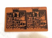
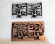
I haven't done this in a while, but I nailed the process perfectly this time. The transfer peeled off leaving a clean sharp pattern for etching. Turned out quite nicely. About 75mm x 45 mm. Now off to drilling a few holes then sling some solder!
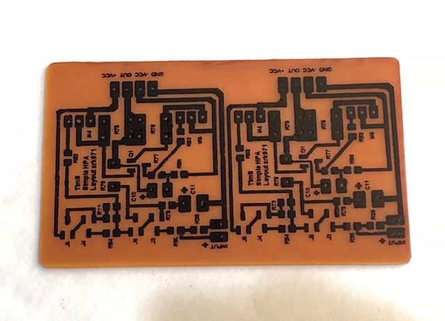
Peeling off laser printed transfer:
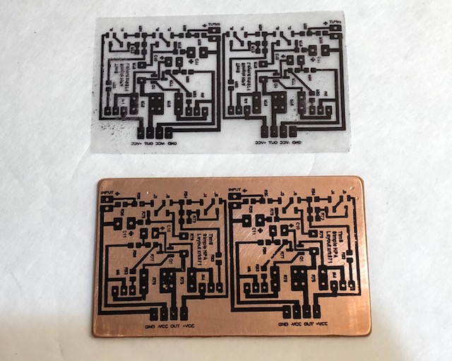
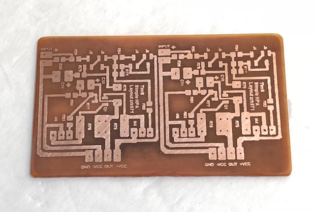
Out of HCl + H2O2 etch bath for 10min:
Wiped off mask with paint thinner and alcohol:
I haven't done this in a while, but I nailed the process perfectly this time. The transfer peeled off leaving a clean sharp pattern for etching. Turned out quite nicely. About 75mm x 45 mm. Now off to drilling a few holes then sling some solder!
Peeling off laser printed transfer:
Out of HCl + H2O2 etch bath for 10min:
Wiped off mask with paint thinner and alcohol:
Attachments
Last edited:
First Sound
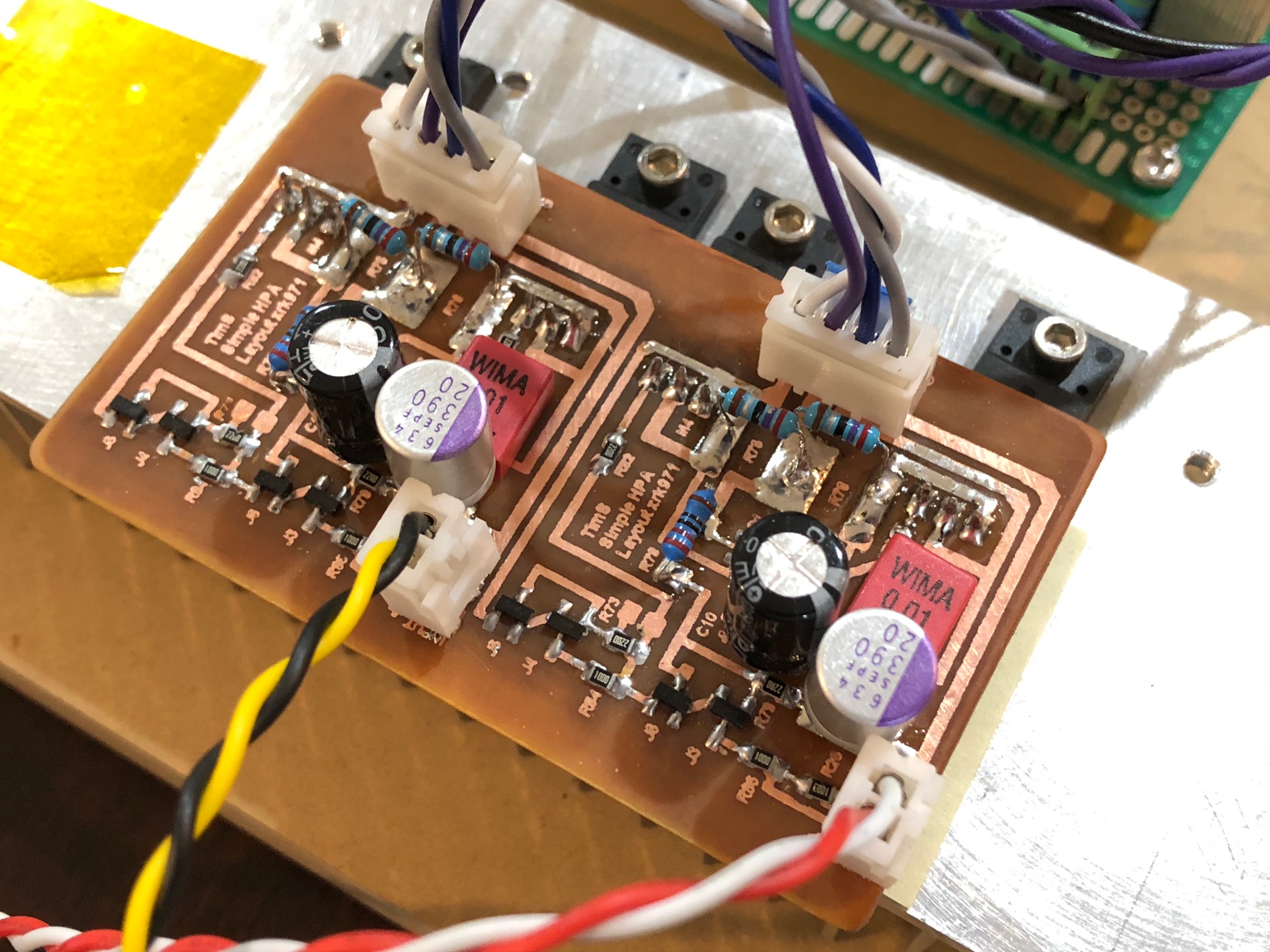
The circuit fired up the first time no issues. I matched the BF862's as required and matched the Vgs of the MOSFETs (2SJ313's were the only P channel TO220's I had around). With 2.7R resistors for R75 and R76, I am getting 115mA bias on one side and 116mA on the other. DC offset is 5mV and -6mV. I did not have any 180R resistors so using 220ohm for R78 and 22R for R79. Just a quick listen with a few songs on my 55ohm OB-1 headphones. Sounds very nice - quite powerful.
Here is the setup with a 50VA 15VAC toroidal transformer and 7815/7915 based PSU:
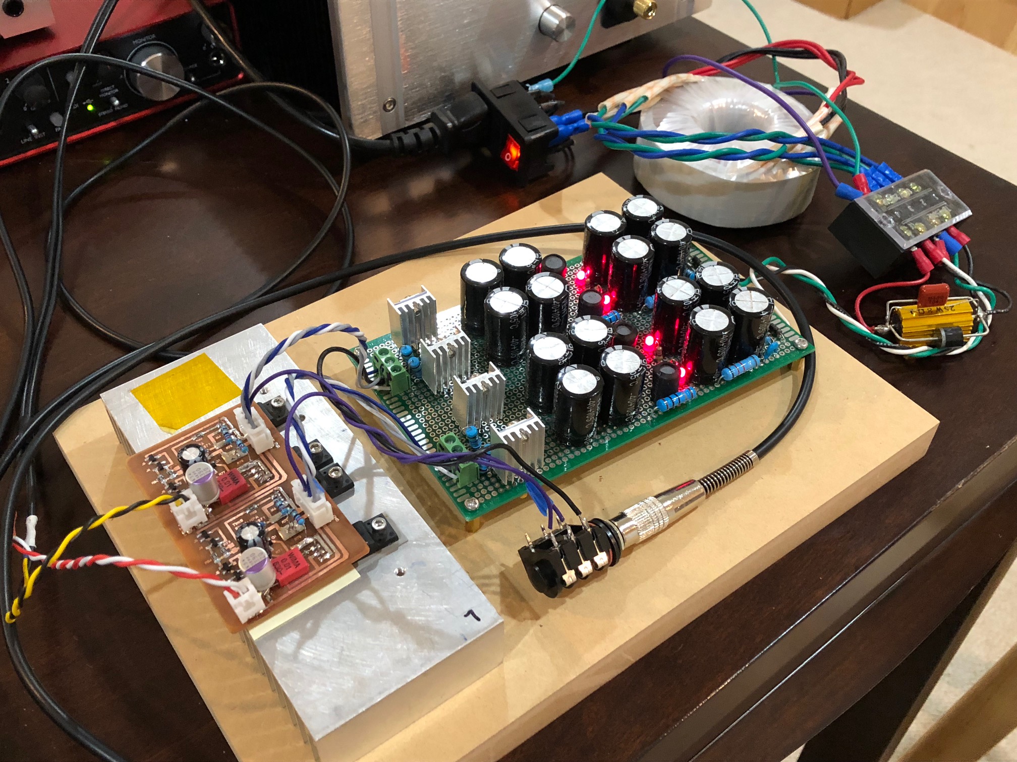
I am using a 390uF OSCON for the shunt cap for low ESR and deeper bass. Bypassed with 0.01uF Wima MKS. Heat dissipation is about 7w total and very well suited for the heatsink currently being used. There are still open pads on R73 to add large values to trim the DC offset if needed.
Now testing with HE400i's - the power is very good, can get way loud. Very clear.
The circuit fired up the first time no issues. I matched the BF862's as required and matched the Vgs of the MOSFETs (2SJ313's were the only P channel TO220's I had around). With 2.7R resistors for R75 and R76, I am getting 115mA bias on one side and 116mA on the other. DC offset is 5mV and -6mV. I did not have any 180R resistors so using 220ohm for R78 and 22R for R79. Just a quick listen with a few songs on my 55ohm OB-1 headphones. Sounds very nice - quite powerful.
Here is the setup with a 50VA 15VAC toroidal transformer and 7815/7915 based PSU:
I am using a 390uF OSCON for the shunt cap for low ESR and deeper bass. Bypassed with 0.01uF Wima MKS. Heat dissipation is about 7w total and very well suited for the heatsink currently being used. There are still open pads on R73 to add large values to trim the DC offset if needed.
Now testing with HE400i's - the power is very good, can get way loud. Very clear.
Attachments


Last edited:
Let me listen to it some more to assess sound quality. From what I have heard so far, it’s a very good amp. It got a lot of bandwidth and I did not install any RFI filtering on the input so suspect it’s an RF amplifier at present when it in a case as I hear a very mild background hiss bit that disappears when the input JST jacks are disconnected. So not intrinsic in the amp. This amp has no problem driving my HE400i’s to ear damaging sound levels without audible distortion - so that is dangerous. You have to be careful how loud you play if you are used to gauging loudness by distortion level. I will get boards made for sure so there will be a GB. TimS made a very good and clever design here with auto DC drift correction that doesn’t require any external opamps.
Btw, I still have some thoughts about your current design:
- 2sk209 bias is a bit on low side, I would want about 4-5mA, but feedback resistor must be lower so ... not sure.
- J5 is not need, and it run very close to its Vgs with M4 vgs.
- R50 is not need.
- C10 is not need too? Why need a bootstrap here? It just a CCS for Q1 ...
- 2sk209 bias is a bit on low side, I would want about 4-5mA, but feedback resistor must be lower so ... not sure.
- J5 is not need, and it run very close to its Vgs with M4 vgs.
- R50 is not need.
- C10 is not need too? Why need a bootstrap here? It just a CCS for Q1 ...
Test Resuts
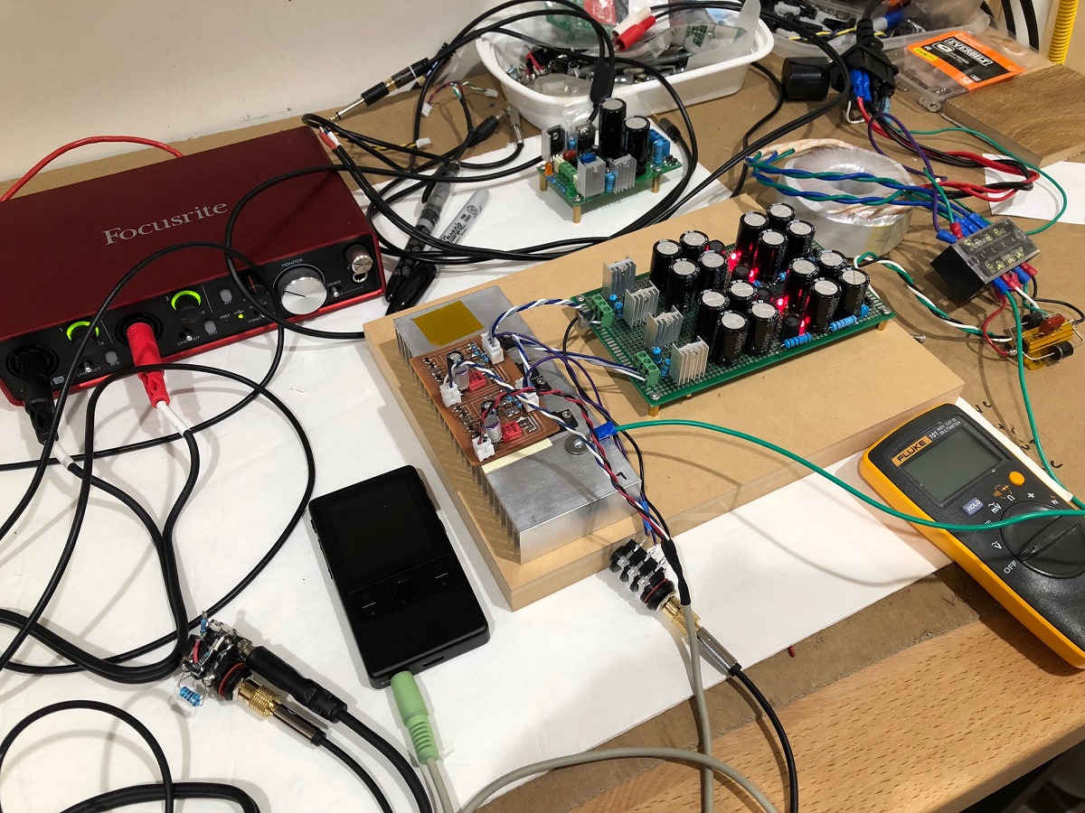
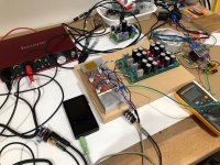
Just had a chance to put the amp through the usual tests. I used a Cayin N3 with a high res 1kHz sine wave file as the source. Focusrite 2i4 for the measurement ADC. Amp is running on +/-15v rails provided by linear 50va trafo and CRCLC with 7815/7915 regulators.
Photo of test setup:
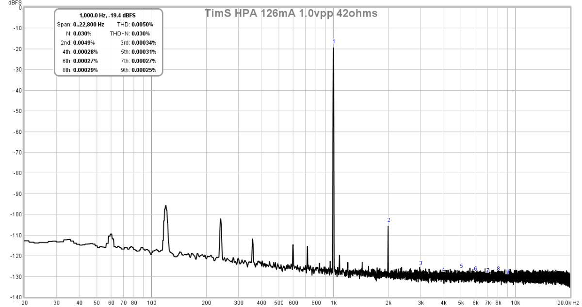
FFT for 1kHz 1.0vpp into 42ohms. THD of 0.005% is much higher than expected, athough all H2. I suspect there is a part in the circuit that is causing some asymmetry that is generating this distortion - although at 0.005% it sounds quite pleasant. It may be the use of thick film SMT resistors in the input stage, or the steel leads on the cheap metal film resistors on the main source/drain resistors and feedback resistor:
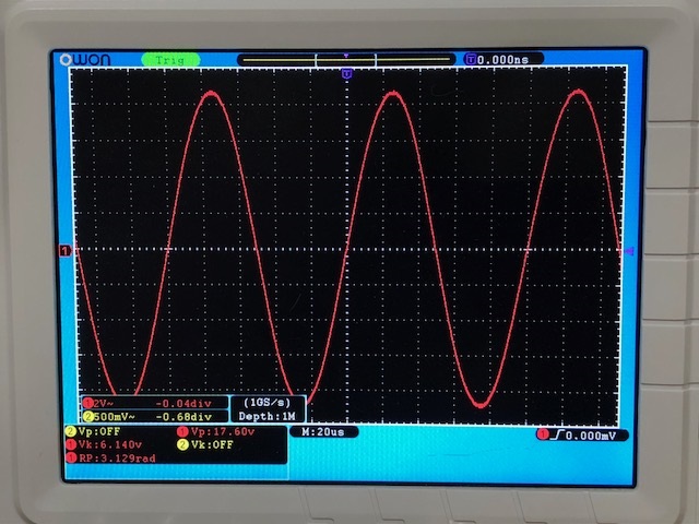
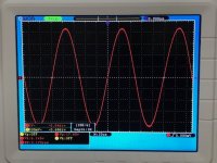
O-scope shot of 1kHz sine wave before clipping showing 17.6vpp into 42ohms (920mW):
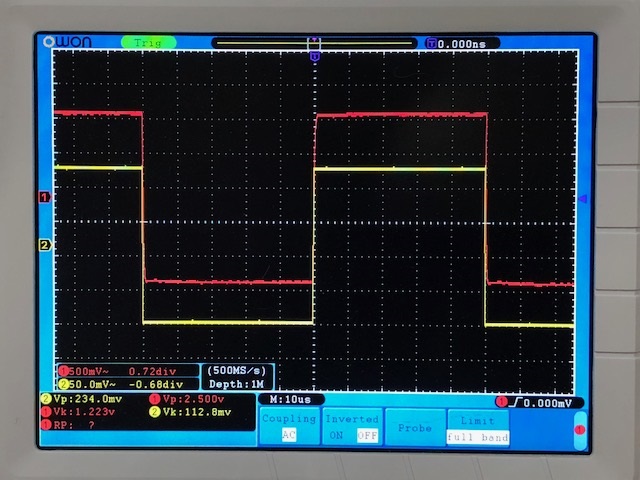
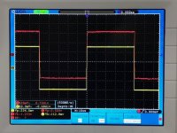
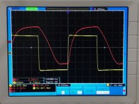
O-scope shot of 10kHz square wave 2.5vpp (yellow is input from function gen, red is amp out):
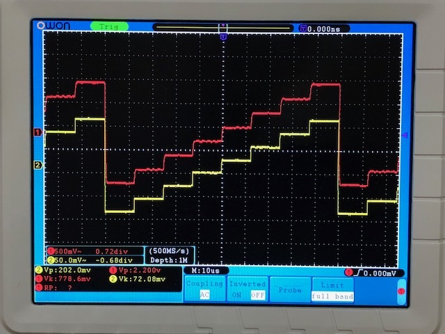
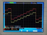
O-scope shot of stair case function for fun:
The amp seems to be pretty clean and oscillation free though.
Just had a chance to put the amp through the usual tests. I used a Cayin N3 with a high res 1kHz sine wave file as the source. Focusrite 2i4 for the measurement ADC. Amp is running on +/-15v rails provided by linear 50va trafo and CRCLC with 7815/7915 regulators.
Photo of test setup:
FFT for 1kHz 1.0vpp into 42ohms. THD of 0.005% is much higher than expected, athough all H2. I suspect there is a part in the circuit that is causing some asymmetry that is generating this distortion - although at 0.005% it sounds quite pleasant. It may be the use of thick film SMT resistors in the input stage, or the steel leads on the cheap metal film resistors on the main source/drain resistors and feedback resistor:
O-scope shot of 1kHz sine wave before clipping showing 17.6vpp into 42ohms (920mW):
O-scope shot of 10kHz square wave 2.5vpp (yellow is input from function gen, red is amp out):
O-scope shot of stair case function for fun:
The amp seems to be pretty clean and oscillation free though.
Attachments
-
 TimS-Prototype-Test-Setup.jpg438.3 KB · Views: 826
 -
 TimS-Prototype-Test-1kHz-Sine-before-clip.jpg140.4 KB · Views: 5,737
 -
 TimS-Prototype-Test-10kHz-Sq-Wave.jpg143 KB · Views: 6,658
 -
 TimS-Prototype-Test-10kHz-Staircase.jpg144.7 KB · Views: 831
 -
 TimS-Simple-HPA-1.0vpp-42ohms-FFT.png79.1 KB · Views: 6,061
Last edited:
I just started a thread to gauge interest for a GB for this HPA here:
Simple High Performance DC Coupled Class A HPA with sub PPM THD
Simple High Performance DC Coupled Class A HPA with sub PPM THD
When operated at a gain of 10X (like this amplifier), all of the power amps in Bob Cordell's book have a bandwidth of 1 MHz and a risetime of ~340 nanoseconds. Since a 250 kHz square wave is 2us hi + 2us low, the (1/3rd) usec risetime is less than 20% of the high time.
You're just accustomed to looking at pre-Y2K IC opamp datasheets, whose bandwidth and slew rate were limited by the very low DC bias currents used in ICs. (also the less than state of the art fabrication technology used.)
Bob Cordell's amps use high performance discrete transistors, operated at healthy bias currents, tuned by good engineering. It's not secret trickery.
- Home
- Amplifiers
- Headphone Systems
- Simple High Performing Headphone Amp