What frequency do you need your gate stopper to work at ?
Anyone eager to find this out, can look at the "Before ferrite" photo (post #19) and the "After ferrite" photo (post #25). Use the risetime-bandwidth equivalency formula, to find the bandwidths of the two different circuits. The ferrite bead needs to have a cutoff frequency well above BW#19 but only slightly above BW#25.
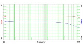
Shrut's recent plot shows the gain-phase with ferrite beads still in place on the output mosfets. It turns out that not all beads are created equal (Orwell, anyone?), and I by chance appear to have picked beads appropriate for the job (honest, a strip of beads-on-leads were sitting on my desk after I saved them from the e-waste bin, and I checked them out on the 4194A for inductance and slotted them in on a whim). They weren't even the ferrite formulation I suspected, but I'll expound on that later. In short, there are 3 ferrite formulations commonly used for beads - only one appears suitable, and it's not the most common variety, either, though still readily available from on-line distributors.
")
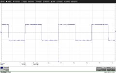
For the last three square wave responses shown, the changes were due to chopping down the values of the two compensation caps. As the bandwidth of the amp increased, I wanted to be sure I wouldn't be running into the pole formed by the output stopper resistors, and the gate + Miller capacitance, hence a smallish bead. An even smaller bead might be appropriate, or a tiny lossy toroid with 2-3 turns of wire. The fastest response was obtained with 12pF for C4, and 680 pF for C2. I still want to see the G-P plot using a more capable instrument than the Venable, as I have seen amps with lovely square wave response display squirreley behavior at or beyond gain crossover . A favorite trick is for the amp response to cross zero, then climb back above zero at a higher frequency. I also want to make sure I'm crossing zero with the proper slope.
Last edited:
Attached are inductance vs. frequency plots for two ferrite beads -on-leads made by Fair-Rite corporation (a US vendor readily available from distributors) of identical size, different composition. The Fair-Rite type 43 mix (or a similar knock-off from another vendor) is the most commonly encountered. This is a Ni-Zn ferrite mix with a wider hysteresis loop and much higher electrical resistivity than the Mn-Zn ferrites used for power duty. The type 61 mix is also Ni-Zn, has much lower permeability than 43, and is used at higher frequencies. Both ferrite mixes display substantial resistive character in the upper ranges of their respective operating frequencies, useful for EMI suppression.
The actual beads shown in the plots are Fair-Rite 2743001112 ans 2761001112, with ferrite beads 3.5mm dia by 4.5 mm long, a convenient size to plonk down in place of s resistor for gate stopper duty. The type 43 bead clearly has too much inductance for the job at hand. The 61 bead is just right. One could also use a much smaller 43 mix bead to get the same inductance as the 61 material. One possibility is Fair-Rite 2643000501, a teensy bead that is 1.95mm dia by 1.5mm long. Two pieces slid on to a piece of bus wire will get the job done. Characteristics for the two beads-on-leads were measured using an HP4194A impedance/gain-phase analyzer with a 16047 test fixture to minimize lead length.
Here are the data sheets for the two beads showing impedance characteristics and behavior with DC bias.
Beads-on-Leads (2743001112) - Fair Rite
Beads-on-Leads (2761001112) - Fair Rite
Attachments
Last edited:
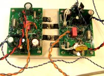
A heads up - the next rev of the headphone amp board is sitting on my kitchen table. I'll be mounting two of them on a suitable heat sink, verifying square wave response, then on to actual listening tests. First headphones to test will be AKG240, with a low impedance but smooth listening characteristics.
Shrut and I have verified function for the latest amp modules. I might try tweaking the transient response to higher heights, but failing that I'll be setting up for listening tests when Shrut gets back from a brutal business trip. Some nice tunes would be an excellent "welcome back".
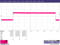
Likely just pickup, as I'm using a "hairball" CMOS 555 oscillator to drive the amp for square wave tests. We're testing in a lab full of switching power supplies under development. I'll be adding proper shielded input cables soon, and a case, once I figure out the logistics.
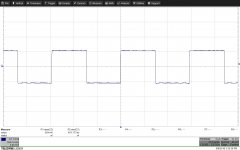
Like I said, I tinkered a bit more with the compensation of the preamp and obtained faster rise and fall times. Compensation values are now C2 - 470pF and C3 - 12pF. The same type 61 ferrite beads are used at the gates of C9 and C10 as in previous measurements. The picture tells the rest of the story.
The rise and fall are quite smooth when examined closely, though the digital scope trace shown here appears to show oscillation at the edges. There are no "squiggles" on the top and bottom of the waveform on my bench setup, and an averaged trace looks even cleaner. Using the usual formula, bandwidth clocks in at 0.34/2.64E^-7 = 1.29 MHz.
The amp wiil now go home to get some proper input cables. Next stop - tunes!
Attachments
Last edited:
Shrut & I just finished auditioning the headphone amp using a Panasonic discman, alternating between AKG k240 Studio and Sennheiser HD598 headphones. The sound is clean and incisive, and ambience is preserved in the recordings where it's present. Next up would be to try a more ambitious signal source. I have a California Audio Icon MkII that might fill the bill
- Status
- This old topic is closed. If you want to reopen this topic, contact a moderator using the "Report Post" button.
- Home
- Amplifiers
- Headphone Systems
- Discrete Headphone Amp.