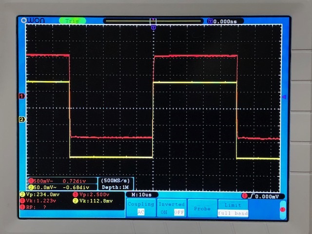
If you look hard, the rise time measurement is at the bottom of the scope picture (~3.8 us). So, that's a bandwidth of 0.34/3.8 E^-6 = ~84.5 kHz I deliberately had Shrut measure that number with the bandwidth calculation in mind.
A level much lower than that required to saturate the output was used to see how the amp would handle a fast signal. The square wave was generated using a little "hairball" circuit built around a TLC555, with a rise time <100ns.
I always use a square wave to check out the large signal response (necessary, but not sufficient to absolutely guarantee stability). Next up will be using a gain-phase analyzer to check out behavior around gain crossover, then it'll be time to try and optimize bandwidth. Doubling the tail current on the input stage could help, as well as upping the current in the driver for the "fake SIT" output (Q11) by shaving resistor values. The compensation values currently in place were ginned up in simulation to keep the little wretch from singing in sim and on the initial breadboard. They might not be either the optimal values or the optimal position for compensation. We'll see.
One of the lessons here is that simulations, though extremely useful, don't necessarily entirely predict the behavior of the beast on the bench. In simulation, the square wave response looked the same no matter which way the drain of the P-Channel device (Q11) was connected. This perhaps might be caused by an actual N-Channel device with lower Vgs that the simulation model. I'll have to look at the sims vs. the actual circuit. I'll also be going back to some of my other amp circuits that use this "fake SIT" arrangement to see if they have similar square wave behavior.
Last edited:
Perfectly happy - the purpose of this thread is to suss out a novel class A circuit and its capabilities/drawbacks, not dick around with a bog-standard opamp I haven't touched in 20+ years. We may end up abandoning this circuit and using something else, but the jury is still out.
Last edited:
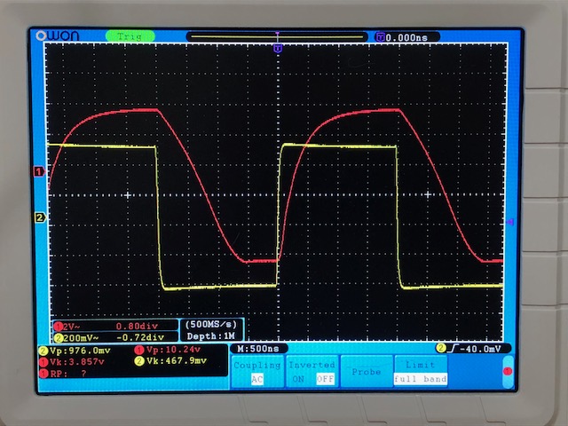
The verdict is "not guilty". After the tweaks I proposed were implemented, the response time pepped up considerably, as can be seen from the attached output waveform. There may still be some remaining juice to be squeezed from this little circuit, but I'll probably save that for the next layout, which incorporates some features to help make the bias more predictable, as well as adding thermal compensation.
I still can't use this thing as a microwave transmitter, but it might make a decent headphone amp after all is said and done. Consider it as a variant of the "Zen" series of circuits.
I still can't use this thing as a microwave transmitter, but it might make a decent headphone amp after all is said and done. Consider it as a variant of the "Zen" series of circuits.
Attachments

I couldn't resist one more compensation tweak, which made things even zippier. I may not be able to see the zero dB crossover point with our hunble Venable gain-phase analyzer, which tops out at 1MHz. Our HP4194A would do the job, but its oscillator output is busted  .
.
.Attachments

As a side note, the compensation values are considerably at variance with those I used to tweak up the compensation in the PSpice simulation, but that's no big surprise. I may try shaving the compensation until I encounter peaking. The simulation took much more HF compensation to avoid peaking.
Try running 10vpp at 250kHz square wave and see how slew rate and ringing and overshoot are. My 10kHz square looks pretty good but at 250kHz it’s pretty ugly. Asymmetry of up vs downstroke is apparent in SE Class A.
10kHz:
250kHz:
Listening to it though on HE400i’s this amp sounds quite superb. Low noise and great dynamics with lots of power. Deep bass and extremely articulate highs.
This is from the TimS simple HPA:
Simple High Performing Headphone Amp
10kHz:
250kHz:
Listening to it though on HE400i’s this amp sounds quite superb. Low noise and great dynamics with lots of power. Deep bass and extremely articulate highs.
This is from the TimS simple HPA:
Simple High Performing Headphone Amp
As a speculative exercise, I used small ferrite beads rather than 47 ohm resistors as gate stoppers for the output mosfets. Using beads (~200 nH) pushes the pole introduced by the stoppers 3X higher in frequency than with the resistors. The beads appear to be doing their job, as there's no spurious oscillation. Positive and negative slew rates are pretty much equal, and the amp is now almost fast enough for prime time.
Attachments
Last edited:
Depends on the industry - SMPS manufacturers use them all the time. If this were in a position (say, on the source or drain) where the bead is forced in and out of saturation, I'd be more worried about the effects. I have found from experience that it takes somewhere around 1/2 A to saturate your typical ferrite bead. Below that current, the bead acts as a reasonably linear inductor, as the huge air gap forces linearity.
As for reasons, resistors are loads cheaper, and they usually do the job ok in linear circuits. I suppose I could also try using a 10-15 ohm stopper. This would similarly move the stopper-gate pole to higher frequencies, but may not "stop" quite as well.
A lot of what I do in this regard will depend on what I see on the G-P analyzer. There it is much easier to see the cumulative phase shifts from "partial" poles.
At any rate, if it ends up sounding gnarly for any reason, I can always replace the beads with resistors again. It's an experiment, after all.
On reflection, it might be interesting to try an inductor wound on a resistor for a gate stopper, similar to the plate stoppers used on tubes like the 807. It wouldn't take many turns to get 200 nH or so.
Wind on a 1 megohm resistor for practice, measure on LCR meter. Adjust winding procedure, wind prototype#2, measure #2. Repeat as necessary; when satisfied, use that winding procedure on a low-ohms resistor. Calculate damping factor of MOSFET gate RLC network, done.
I am pleased with this LCR meter although I bought mine from eBay instead of Amazon. (I actually prefer my AADE LCR Meter II, but its manufacturer passed away, and they're no longer available new).
I am pleased with this LCR meter although I bought mine from eBay instead of Amazon. (I actually prefer my AADE LCR Meter II, but its manufacturer passed away, and they're no longer available new).
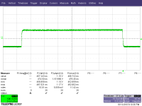
This is a 100kHz-40MHz scan of a 47 ohm 1/4W CF resistor with 12 turns of 34 AWG double coated magnet wire. There is a little roll-off at the uppper end, likely due to the distributed capacitance of the winding. It may actually resonate somewhere off in la-la land.
The scan was made using an HP4194A Impedance/G-P analyzer. I'm buying one of these when I hang out my own shingle. A huge, hulking beast it is, but very reliable. No new machine that I know of has the same functionality (esp the 40MHz capability on the G-P analyzer plus the impedance function), certainly not from Agilent.
The scan was made using an HP4194A Impedance/G-P analyzer. I'm buying one of these when I hang out my own shingle. A huge, hulking beast it is, but very reliable. No new machine that I know of has the same functionality (esp the 40MHz capability on the G-P analyzer plus the impedance function), certainly not from Agilent.
Attachments
Could such RL gate stoppers prove useful for general use? I make a lot of SMT layouts now and see small SMT ferrite beads all the time. One could even stack one right on top of a typical 47R to 220R gate stoppers that are being used now. Will it allow use of lower R values then?
I guess trying to simulate it on LTSpice first to see how predicted square wave goes.
I guess trying to simulate it on LTSpice first to see how predicted square wave goes.
Last edited:
Why not ask Mr. Nelson Pass why his MOSFET amplifiers use resistor gate stoppers instead of ferrite beads? I've become familiar with his "FirstWatt M2" amplifier (link)-- the "M" in the name indicates that the output stage uses MOSFETs -- and all gate stoppers in the entire M2 amplifier are resistors (221 ohms) rather than ferrite beads. Aren't you the least bit curious why a grizzled veteran does what he does and doesn't do what he doesn't do?
Aren't you the least bit curious why a grizzled veteran does what he does and doesn't do what he doesn't do?
"Grizzled veteran"--I like that.

- Status
- This old topic is closed. If you want to reopen this topic, contact a moderator using the "Report Post" button.
- Home
- Amplifiers
- Headphone Systems
- Discrete Headphone Amp.