A long time ago I worked as a designer for low cost consumer mixing panels, had to cut out any possible component for cost. until the moment of truth came and AM reception was heard on the phono input. a sect in amsterdam claimed that the deveil could be heard between tracks. the fix was a ferrite bead on the base pin of the transistor, but it had to be glued as the ferrite movement/ratlle could be heard as magnetic induction/microphonics.
I have already been accused of fiddling with the original JLH circuit.
So I am not going to add a ferrit bead.
In the original circuit as posted by the deleted link in post #1, there is a RC at the input to filter off any RF pickup.
So I'll leave you to add that yourselves if so wish.
Patrick
.
So I am not going to add a ferrit bead.
In the original circuit as posted by the deleted link in post #1, there is a RC at the input to filter off any RF pickup.
So I'll leave you to add that yourselves if so wish.
Patrick
.
Attachments
still the loop gain is very poor. the transistor output current is divided between the load and the feedback resistor, then at the entry into the emitters there is another division due to the gain dividing resistor. no current gain in the input transistors, only the beta of the output transistors. that is why we have to rely on linear beta transistors.
> The 2n2 cap has another function, to keep the hf loop gain high by grounding the bases of the input transistors.
Correct. So the usual trick of increasing the cap to limit bandwidth for stability does not work, because it actually increases OLG at HF.
Took me a little while to realise that.
> still the loop gain is very poor.
Already explained in the article. See post #35.
> the transistor output current is divided between the load and the feedback resistor,
If you can make it drive 30R load, 1k in addition is no issue.
> no current gain in the input transistors, only the beta of the output transistors.
Hence the use of Darlingtons in the modified version.
> that is why we have to rely on linear beta transistors.
Linear beta transistors is ALWAYS a good idea for any analogue audio circuits.
Patrick
I have already been accused of fiddling with the original JLH circuit.
So I am not going to add a ferrit bead.
In the original circuit as posted by the deleted link in post #1, there is a RC at the input to filter off any RF pickup.
So I'll leave you to add that yourselves if so wish.
Patrick
.
It could be an idea to put the RC filter before the potentiometer. That way it won't be a variable filter.
You can use a split-resistor approach to control the hf olg (just insert a couple-100ohms resistor betwenn the hot end of the cap and inp. transistors bases, aka "base stopper"). Will need a spice probing first and after that a hf square-wave oscope test - and finetuning for the optimum value.> The 2n2 cap has another function, to keep the hf loop gain high by grounding the bases of the input transistors.
[/COLOR]Correct. So the usual trick of increasing the cap to limit bandwidth for stability does not work, because it actually increases OLG at HF.
Took me a little while to realise that.
...
The original version will stay original, as far as I am concerned.
But of course indivuduals can decide how they want it.
Our modified version is now stable without caps in the feedback, with or without load.
And you can see the clean frequency response in post #80.
Cheers,
Patrick
But of course indivuduals can decide how they want it.
Our modified version is now stable without caps in the feedback, with or without load.
And you can see the clean frequency response in post #80.
Cheers,
Patrick
As promised, including frequency responses with or without load.
You can see when when not loaded the amp has a slight (1.5dB) overshoot at ~ 2MHz.
But it is now kept stable by the Zobel network.
At 30R load, it is stable on its own.
Patrick
.
I'll probably make a through hole version. Will I possibly run into oscillation issues?
There is only one way to find out.
Patrick
:smile_phones:
As you have seen, if 5mm extra length on a transistor leg is the cause and cure of oscillation, then it is also highly layout dependent.
Which is why we Beta test the revised PCB by someone else, just to catch these pitfalls.
Which is also why we are so particular about layout (see the F5-HA for all those uneducated copies).
Of course I encourage you to do your own PCB for a leaded version.
But be prepared that you will have issues and that you have the skills, time and patience to handle them.
Having said that, it probably only applies to the modified version.
I trust Mr. Linsley Hood would have thoroughly tested his.
And maybe the original version is less prone to oscillation.
But it will probably also have a hard time driving low impedance loads.
So back to my previous statement, there is only one way to find out.
It is part of the fun of DIY.
")
Patrick
Which is why we Beta test the revised PCB by someone else, just to catch these pitfalls.
Which is also why we are so particular about layout (see the F5-HA for all those uneducated copies).
Of course I encourage you to do your own PCB for a leaded version.
But be prepared that you will have issues and that you have the skills, time and patience to handle them.
Having said that, it probably only applies to the modified version.
I trust Mr. Linsley Hood would have thoroughly tested his.
And maybe the original version is less prone to oscillation.
But it will probably also have a hard time driving low impedance loads.
So back to my previous statement, there is only one way to find out.
It is part of the fun of DIY.
Patrick
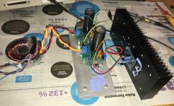
At last, after the oscillation problems, I got it all together and had some time to listen to the Xen version of the JLH headphone amp. The circuit is really simple to build as you get familiar with smd soldering with only few parts in this Xen version. The DC offset on the output was quite easy to set to a level of +-10 mV and the bias was configured to 150 mA.
So here are my first impressions with a basic power supply (common for both channels). Usually my first impressions don’t change much.
It seems to be a very musical and pleasant to listen to. You easily forget yourself in listening and in no time the song ends and you have no notes about sound quality in mind. I would say that’s a pretty darn good feature for a headamp.
What else can I say... Soundstage is wide, sound signature is clear and crisp, very effortless. Bass is tight, but not quite as deep as with UTHAiM, still very good. Vocals are good but I think some contestants are better on this regard. The highs are really sparkling, but not too much.
Great design once again. There seems to be some magic with this simple circuit!
My test setup was the following:
- Raspberry Pi with Moode Audio player software => Ian Canada's isolator board => Allo Kali reclocker board => I2S output
- I2S input to DDDAC DA-converter (a single Tent shunt board version)
- All music files were FLAC 16bit/44.1kHz ripped from original CDs with dB Power Amp software.
- The volume levels were matched by feeding a 1 kHz test signal to the DAC and the voltage was measured from the headphone jack while my Audeze LCD-2 phones were connected.
- Volume control was the same for both headamps: Arduino based LDR volume and source selection controller.
- My headphones used for the test were Audeze LCD-2.2 Fazor
Many thanks for the Beta test and the listening impressions.
Maybe some photos of your final test setup ?
The updated BoM and Gerber files will be posted in a few days.
The original JLH version using the same PCB will also be beta tested.
But this might take a while longer.
Cheers,
Patrick
Maybe some photos of your final test setup ?
The updated BoM and Gerber files will be posted in a few days.
The original JLH version using the same PCB will also be beta tested.
But this might take a while longer.
Cheers,
Patrick
As promised here the Gerber files.
The Bill of Material in Post #35 has the following changes for the XEN modified version :
R13,14 -> 470R
Cf1,2 -> leave open
Rz -> 5.1R
It is important that you only use 5mm standoffs to keep the legs of the output transistors short.
The original JLH version has yet to be tested, as mentioned before.
Happy building,
Patrick
.
Attachments
Patrick, forgive me again. Just looking through the BOM for these boards and once again it's one resistor value that is difficult.
3R3 thin film resistors for R11/R12 are very hard to find even in 1206 - can these be thick film types or is there some margin to play with values for these say to 4R7?
As MELF were specified, I take it they are critical?
They are on the transistor emitters so would a certain selection of HFE allow a different resistor value?
- Home
- Amplifiers
- Headphone Systems
- The REAL John Linsley Hood Headphone Amplifier