All mosfets made for switching apps suffer from Spirito instability, like the one I used C2M1000170D (1700V 69W 5A, 1Ω 200pf mosfet)Do your MOSFETs suffer from Spirito instability (which is basically the same as thermal second breakdown: self destruction by local heating causing increased local current causing even worse local heating and so on), or is it only the overall current at a given VGS that increases too much? In the latter case, you might be able to solve it by changing your circuit design, by adding source degeneration for example (or by any other technique that senses and controls the drain current). With Spirito instability you can only look for a more suitable MOSFET type with a better SOAR graph.
You can tell when a) power dissipation is low vs max current, while rdson is low.
Those few mosfets designed for linear operation are at at least 2-4 times more expensive and have 5 or more times higher input capacitance that makes them more difficult (and more expensive) to drive, but apparently I will have to use them, because you can't tell whether the same low current is mostly consumed by one cell or split to 100 cells on the same die on a switching one.
There are 3 1500V linear mosfets from IXYS of which the most appropriate IXTH2N150L (1500V- 2A-290W-15Ω-1400pf) is not available (on backorder for January), but I saw a Chinese distributor (DIGSEMI) that is listed as having 5000 pieces available- not sure if it is to be trusted though.Actually IXYS are doing something about it, albeit only for 1000V devices.
Jan
IXTH 2N150L Price & Stock | DigiPart
Still, I'd prefer 1700V ones as 1500V max V is too close to 1400V output.
Yes, 1% THD with an odd harmonic at 0.5% might sound worse than 1%THD with an odd harmonic at 0.1%, but obviously there is a threshold under of which no harmonics are audible, even or odd ones, due to masking. Still, I'll see if I can do something about it -for the sake of perfection.2nd hd 1% is not damaging as 3rd or 5th 0,5%.
distortion profile of a device is what matters, total thd number gives no clue how things are
All mosfets made for switching apps suffer from Spirito instability, like the one I used C2M1000170D (1700V 69W 5A, 1Ω 200pf mosfet)
You can tell when a) power dissipation is low vs max current, while rdson is low.
Those few mosfets designed for linear operation are at at least 2-4 times more expensive and have 5 or more times higher input capacitance that makes them more difficult (and more expensive) to drive, but apparently I will have to use them, because you can't tell whether the same low current is mostly consumed by one cell or split to 100 cells on the same die on a switching one.
The SOAR looks OK, though, and as it is a post-2000 datasheet, any Spirito instability should be in the SOAR graph. (In the late-1990's, power MOSFET manufacturers had increased the transconductances enough to cause the Spirito stability problem, but they didn't show it in the datasheets because they were unaware of it themselves.)
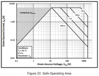
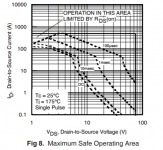
I've attached the SOAR graphs of the C2M1000170D and of the IRFB3307ZPbF datasheet, which has clear Spirito instability.
Attachments
I think I read somewhere that IRF does this, but that doesn't mean that when another company omits it you should feel safe!The SOAR looks OK, though, and as it is a post-2000 datasheet, any Spirito instability should be in the SOAR graph. (In the late-1990's, power MOSFET manufacturers had increased the transconductances enough to cause the Spirito stability problem, but they didn't show it in the datasheets because they were unaware of it themselves.)
I've attached the SOAR graphs of the C2M1000170D and of the IRFB3307ZPbF datasheet, which has clear Spirito instability.
EDIT: I just realized something.
Look at that graph again: not even "DC" is mentioned on their SOA graphs (in other parts too), which means that the larger area is 100ms as stated, NOT DC and the upper area is cropped and limited to 10μs as too short pulses can also create hotspots!
And you'll have to derate it for the working case temperature.
Clearly, a switching-only device. Even the brand implies it: "WolfSpeed" (which might be great on their intended fast applications of course).
Compare this to the IXYS' linear graphs, with the second one rated and guaranteed at a realistic temperature of 75ºC:

One part is rated at 5A and 69W and this one at 2A and 290W!
Of course one could do a stress-test to find out, like providing a higher current than the desired one vs temperature leaving a small safety area calculated acording to specs and see if the device survives. If any hotspots are created, they will quickly cross that safety margin.
But since I will have to order from abroad, I'm a bit reluctant -I prefer to pay double the price for 8 mosfets and be safe.
Last edited:
I think I read somewhere that IRF does this, but that doesn't mean that when another company omits it you should feel safe!
It would be really stupid if they deliberately published unrealistic SOAR curves, though. When a company deliberately publishes SOAR graphs without the effect of Spirito instability while their MOSFETs suffer severely from Spirito instability, they are lying about the performance of their MOSFETs. Chances are that their customers will then sue them when they find out.
EDIT: I just realized something.
Look at that graph again: not even "DC" is mentioned on their SOA graphs (in other parts too), which means that the larger area is 100ms as stated, NOT DC and the upper area is cropped and limited to 10μs as too short pulses can also create hotspots!
100 ms is long compared to the thermal time constants in the thermal transient impedance graph that is to the left of the SOAR graph in the datasheet, so the 100 ms SOAR should be pretty close to the DC SOAR - except that the overall power must be derated a bit further for DC.
And you'll have to derate it for the working case temperature.
Clearly, a switching-only device. Even the brand implies it: "WolfSpeed" (which might be great on their intended fast applications of course).
Of course you have to derate it; it has been industry practice for decades to specify everything at 25 degrees case temperature, both for switching transistors and for transistors meant for non-switching applications.
Compare this to the IXYS' linear graphs, with the second one rated and guaranteed at a realistic temperature of 75ºC:
g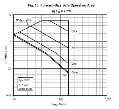
One part is rated at 5A and 69W and this one at 2A and 290W!
Of course one could do a stress-test to find out, like providing a higher current than the desired one vs temperature leaving a small safety area calculated acording to specs and see if the device survives. If any hotspots are created, they will quickly cross that safety margin.
But since I will have to order from abroad, I'm a bit reluctant -I prefer to pay double the price for 8 mosfets and be safe.
Fair enough, do whatever you like.
I just read that application note that Jan Didden dug up. I find it strange, because in that application note IXYS claims that the SOAR graphs they publish for their switching transistors don't include the Spirito instability issue and are therefore way too optimistic on the bottom right part. It is very unusual for a company to write in a public document that their specifications are complete and utter lies.
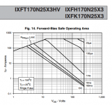
However, when I look at the SOAR graph of a random IXYS transistor with very low on resistance (very low on resistances usually indicate trouble), the allowable current does drop faster than inversely proportionally with increasing current. So apparently the datasheet graph does include the Spirito issue, as it should, even though their application note claims otherwise. Change in company policy, maybe?
However, when I look at the SOAR graph of a random IXYS transistor with very low on resistance (very low on resistances usually indicate trouble), the allowable current does drop faster than inversely proportionally with increasing current. So apparently the datasheet graph does include the Spirito issue, as it should, even though their application note claims otherwise. Change in company policy, maybe?
Attachments
LIfe experience dictates that there is a lot of gray areas in law and marketing, and a lot of risk designing something, so if one wants to be on the safe side, he should better avoid those gray areas and as much risk as possible.It would be really stupid if they deliberately published unrealistic SOAR curves, though. When a company deliberately publishes SOAR graphs without the effect of Spirito instability while their MOSFETs suffer severely from Spirito instability, they are lying about the performance of their MOSFETs. Chances are that their customers will then sue them when they find out.
WolfSpeed for example doesn't lie, they never mentioned DC operation. You can't sue them for something they don't claim.
It seems close to DC, yet the company does not mention DC for a reason, despite they want to sell more parts.100 ms is long compared to the thermal time constants in the thermal transient impedance graph that is to the left of the SOAR graph in the datasheet, so the 100 ms SOAR should be pretty close to the DC SOAR - except that the overall power must be derated a bit further for DC.
That's more likely than assume they didn't mention DC because they didn't care. Besides, you have all indications that support this, from the device's parameters I mentioned previously that suggest a switching-only device, to the company's exclusive switching orientation and total lack of mentioning "DC" and "linear" about their mosfets in contrast to other companies.
Many companies admit/warn in various documents that in general the SOA graphs are -or were at least up until recently, overestimatiing their parts capabilities. Again it's a matter of keeping a safe margin, starting at least from what they explicitly state, rather than from assumptions.I just read that application note that Jan Didden dug up. I find it strange, because in that application note IXYS claims that the SOAR graphs they publish for their switching transistors don't include the Spirito instability issue and are therefore way too optimistic on the bottom right part. It is very unusual for a company to write in a public document that their specifications are complete and utter lies.
However, when I look at the SOAR graph of a random IXYS transistor with very low on resistance (very low on resistances usually indicate trouble), the allowable current does drop faster than inversely proportionally with increasing current. So apparently the datasheet graph does include the Spirito issue, as it should, even though their application note claims otherwise. Change in company policy, maybe?
Speaking of margins, in my case one part's max power is close to the max power required and could suffer instabilities, the other has plenty of room and it's stable, but its max voltage (1500) is close to the voltage required (1400) so I would have to provide about 1450V stabilized voltage (+-725V) and get undistorted 1400Vpp (700V peak)...
Last edited:
http://ixapps.ixys.com/DataSheet/DS100498C(IXTH-T02N450HV).pdf has DC SOA @75 C ~30ma @ ~1500 V by eyeball
US$20 ea, no stock, 14 week leadtime - whats not to like?
its HV pakcage option does bring up another issue - lead spacing
the lead spacing of TO-220 or even 247 package are way below creepage distances in safety standards for kV
do we pot (vacuum degas), or hand paint - how to get between the leads and the heat sink, void free, with 100% reliability
Last edited:
The lead spacing on _that_ part are odd, to handle the 4KV on the Drain.
"Creepage" is generally to keep users safe from equipment. The equipment can arc itself all it wants. Mostly we don't worry because air won't arc <300V. Yes, at 4KV I would be curious and cautious.
Moisture-FREE oil is good stuff.
"Creepage" is generally to keep users safe from equipment. The equipment can arc itself all it wants. Mostly we don't worry because air won't arc <300V. Yes, at 4KV I would be curious and cautious.
Moisture-FREE oil is good stuff.
If it was linear and costed at least 25% less, It could be a good alternative (although I'm not yet sure about the peak current required -30mA seems too close).http://ixapps.ixys.com/DataSheet/DS100498C(IXTH-T02N450HV).pdf has DC SOA @75 C ~30ma @ ~1500 V by eyeball
US$20 ea, no stock, 14 week leadtime - whats not to like?
As a switching one that costs 4 times more (2x the linear one) = too expensive, and who waits 14 weeks?
")
As for the HV isolation, that obviously needs some thorough investigation before using 4 - 4.5Kvolts, to avoid turning the amp to a fancy tesla generator
I think that if you use one of these (mica replacements) preferably along with the ISOPLUS-i4-PAK-3 package, you'll be OK.
The last one -SPC-10 seems to be more suitable, as it has the lowest dielectric constant, which obviously translates to 3.7 times more capacitance vs what you'd get with air for the same area and distance (or material thickness). That parasitic capacitance should be simulated too.
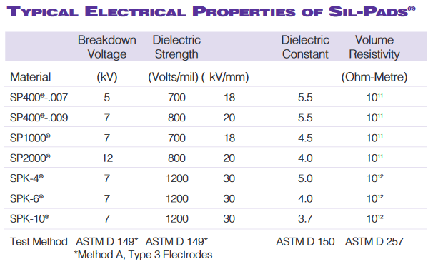
http://www.farnell.com/datasheets/99609.pdf
Last edited:
Elvee came up with some interesting design [picture]
Same approach, but very different.
Although I'm trying to move to quasi complementary for better performance.
..but I keep turning back for improvements.
-What is the distortion at 1Khz and 20Khz?
-What current does it draw?
-What is the frequency response?
(measured with a capacitive load of course)
-Are the mosfets "real"?
-Do they include the input capacitance?
(I have manually added the input capacitance to be sure as I suspect it is not included, although the models are official)
http://www.diyaudio.com/forums/soli...irect-drive-esl-amp-please-4.html#post5228127
Ask the original designer.
See also post #25, 28 & 34.
Patrick
Ask the original designer.
See also post #25, 28 & 34.
Patrick
Last edited:
Elvee came up with some interesting design:
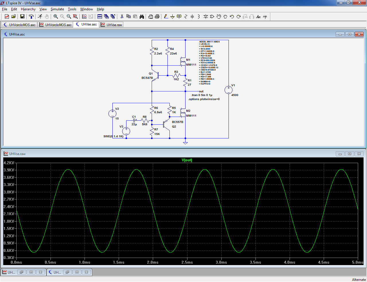
I see a 22mA ccs on top, bottom Schaded fetriode µ=453 (6M8/15k)
PNP to FET is nice, but i dislike the dividers wiring - confusing
I haven't tried the above design, but I can tell that it obviously suffers from many "diseases", like excessive distortion, inadequate power bandwidth, etc.
I have personally put a lot of work to reach and further lower the previously mentioned 0.025% -by using different techniques.
But I recently came up with a quasi-complementary design with the following current specs: 0.004% THD with reduced high-order harmonics at up to 20KHZ, full power bandwidth of 1.4KV (from 1500V power supply) , 250pf load, mosfets with 1400pf input capacitance (instead of 200pf of the previously mentioned Cree one) and clean square-wave response. In LTspice of course, not real-life yet.
Still I have a lot to do, from making it a dual-supply one, to lowering it further to <0.001%, to ensuring perfect stability in all conditions etc.
Another spec I'd like to add is a double headphone drive capability (>500pf) for dual-listening with a friend.
(BTW, Stax amplifiers are in the order of 0.01% and like any other ES amp, are only rated at 1Khz -which tells nothing about how the amp behaves at the end of the audio band -it might well be in the order of 0.1-0.2% @20Khz, or more -I've encountered that in some of my experiments). Or not.
The funny thing is, that as the difficulty rises exponentially in all sectors, it almost feels like fighting in a jungle of wild devices and parameters
One such parameter is phase shift. Despite the fact that my current design has a power bandwidth of 790Khz(-3db) with the load, it has a phase shift about 1.8 degrees at 20Khz -but I'm not sure how bad this is.
So the question is: what is the required maximum phase-shift at 20Khz for a high-end amp nowadays? I have looked online and in books and I can't find any standards or references about it.
Last edited:
I can't give you a direct answer to that either, but I can tell you that deviation from linear phase is rather more important than phase shift by itself; who cares when the music is played a microsecond later? You'll probably find that the deviation from linear phase is extremely small in your design; low-pass filters usually have almost linear phase far below their cut-off frequency.
It's 1.8 degrees for a 20Khz period, vs almost zero degrees for a 20hz period =obviously 1/1000 of 1.8 degrees at 20hz as you said, which is constant yes, and relative to the bandwidth. The question is what is considered too much and what is considered "normal" for a high-end amplifier.
- Status
- This old topic is closed. If you want to reopen this topic, contact a moderator using the "Report Post" button.
- Home
- Amplifiers
- Headphone Systems
- Electrostatic Amp THD Specs/Measurments for the Full Audio Band ?