Patrick,
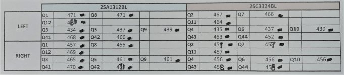
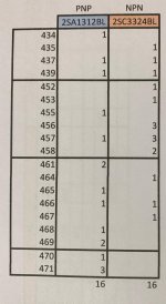
Please give a look to the table below, that is the best that I can get after matching 100 2SC and 2SA.
Not really lucky, I just have 16 2SA that can be somehow matched.
I think that they are matched enough (the worse are the CCS ones that are ~2,5% unmatched between NN and PP) but please let me know
Thanks and Regards,
Enrico
Attachments
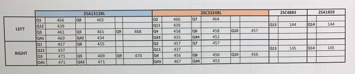
Your best N-P matched pairs should be used for Q1,2 and Q7,8.
Then next best N-P match for Q11,12 & Q13,14 (Sanken).
Then NNN & PPP for Q4,6,10 & Q3,5,9, not must for perfect N-P match here (5% is OK, 2% is perfect).
And then next NN & PP for Q41~44.
But already mentioned in the PDF P.5 ??
Patrick
Then next best N-P match for Q11,12 & Q13,14 (Sanken).
Then NNN & PPP for Q4,6,10 & Q3,5,9, not must for perfect N-P match here (5% is OK, 2% is perfect).
And then next NN & PP for Q41~44.
But already mentioned in the PDF P.5 ??
Patrick
Patrick,
It’s clear for Q43/Q44 moves
Not really for the first proposal “swap Q1, 2 of the Left with Q7, 8 of the right.
As far I understand Q1, 2, 7 and 8 should be matched as NN and PP as well and I was sure that my proposal was correct... what I miss?")
Thanks for your patient
Regards,
Enrico
It’s clear for Q43/Q44 moves
Not really for the first proposal “swap Q1, 2 of the Left with Q7, 8 of the right.
As far I understand Q1, 2, 7 and 8 should be matched as NN and PP as well and I was sure that my proposal was correct... what I miss?
Thanks for your patient
Regards,
Enrico
Last edited:
Patrick,
Thanks for the heads up and fair warning about the difficulty of this project. Maybe I can use this as an excuse to pick up some new tools and knowledge
All of my matching is complete - Regulators are built and seem to be functioning perfectly. +/-14.54 almost completely across the board.
I’m almost wrapped up with the two SLA amplifier boards.
Is anyone able to give me the idiots guide to biasing the amplifier circuit? I’ve done a fair amount of reading through this thread and others on the forum and the closest I’ve gotten is to read the voltage across the emitter resistor - am I in the ballpark?
Hi Patrick,
Somehow (arghh!) I missed to buy the ADA2202 for the protection board... I still have the OPA2209 from the previous protection board. I give a look to the datasheets and as far I can see (pin out and operating voltage) seems to be ok.
May I use the OPA2209 without changes on other parts?
Thanks and Regards,
Enrico

Patrick,
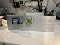
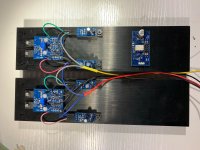
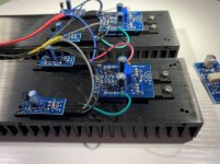
I took some time but I am there...
The 4 regulator are done, tested and trimmed the R1 to get:
+14.995 V
+15.006 V
- 14.934 V
- 14.973 V
The 2 main boards are tested:
- without CCS I get +61 and +42mV.
- with the CCS AND the 2 R44 trimmed I can get +4~+7mV and -3~-6mV
The SHPP is completed (and tested) and the chassis is work in progress
Regarding the passive Xfeed, if I am not wrong the 2 310K should should be installed. Can you please confirm?
What I need now is the motherboard to complete the PSU but I think it will take some weeks
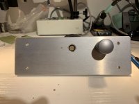
I attached some picture... as you can see I was provident to buy the 2nd LEMO
Enrico
I took some time but I am there...
The 4 regulator are done, tested and trimmed the R1 to get:
+14.995 V
+15.006 V
- 14.934 V
- 14.973 V
The 2 main boards are tested:
- without CCS I get +61 and +42mV.
- with the CCS AND the 2 R44 trimmed I can get +4~+7mV and -3~-6mV
The SHPP is completed (and tested) and the chassis is work in progress
Regarding the passive Xfeed, if I am not wrong the 2 310K should should be installed. Can you please confirm?
What I need now is the motherboard to complete the PSU but I think it will take some weeks
I attached some picture... as you can see I was provident to buy the 2nd LEMO
Enrico
Attachments
> Regarding the passive Xfeed, if I am not wrong the 2 310K should should be installed.
Correct, if you are using 10k pot.
I doubt you will hear any difference even if you did install them.
> What I need now is the motherboard to complete the PSU but I think it will take some weeks
You should listen first, even with lab supply.
Patrick
Correct, if you are using 10k pot.
I doubt you will hear any difference even if you did install them.
> What I need now is the motherboard to complete the PSU but I think it will take some weeks
You should listen first, even with lab supply.
Patrick
- Home
- Amplifiers
- Headphone Systems
- The Pioneer Super Linear Circuit