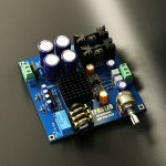
I bought this TPA6120 kit from a Chinese vendor.
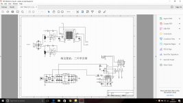
Unfortunately the kit does not come with a component list and the schematic is in Chinese.
I am left with 6 capacitor positions on the PCB that I have to guess what goes where.
CD4, CD5, CD10 & CD12 are paralleled across the outputs of the 7815 and 7915 regulators.
This kit contains 5 x 47uF/25V electrolytics that look as though they should fit. However isn't 100uF (2 x 47uF) a bit too high on the output of the regs ?
CD1 & CD2 are input decouplers paralleled by 1uF poly caps.
The kit contains more 47uF and 470uF caps that would fit in these positions.
Attachments
The only caps left over in the kit are:-
47uF/50V x 5
470uF/25V x 2
47uF/50V x 2
47uF/50V x 2
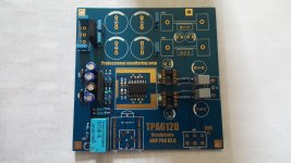
And, yes, there are only the six unoccupied positions on the board.
Ignore the empty CD6, CD7, CD9 & CD11 positions, they are the far bigger reservoir caps after the bridge.
47uF/50V x 5
470uF/25V x 2
47uF/50V x 2
47uF/50V x 2
And, yes, there are only the six unoccupied positions on the board.
Ignore the empty CD6, CD7, CD9 & CD11 positions, they are the far bigger reservoir caps after the bridge.
Attachments
Its not helpful now but I saw that kit and chose another because I couldn't see any docs, schematic or guide to values on the overlay. There are a few varieties of that design from different Chinese kit producers and you may be able to reason out the appropriate values from cross-checking other pics of similar layouts.
My kit is somewhat different and has 2 pairs of regulated supplies of +/-15V each, bypassed with 330uF on each reg. input pin. The cap. values seem to vary quite a lot with whatever fits and is available though. (200-680uF was printed on the board in this case).
You may want to try the headphone forum, for more folk who are familiar with this sort of problem though.
I bought this TPA6120 kit from a Chinese vendor.
Ahhhh.. Can't cheat an honest man
")
dont worry, place these bigger capacitors on board ...
if you bought it from china, opamps are most probably faked, so use something own from genuine source ...... or use it without opamps (my TPA is always without opamp), if you dont use opamp, connect with jumper signal input in opamp with opamp output ...
if you bought it from china, opamps are most probably faked, so use something own from genuine source ...... or use it without opamps (my TPA is always without opamp), if you dont use opamp, connect with jumper signal input in opamp with opamp output ...
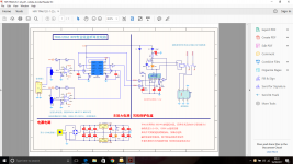
Strange that the input coupling 'lytics(CD1 and CD2) look to have 5mm LS and perhaps a 10mm o.d. implying that a larger value cap be used in those positions. I would think 47uF would be more than sufficient in those locations.
Some think 100uF after those regulators is fine, but in my experience a smaller value is better. I would personally use 22uF-47uF for CD5 and CD10. Paralleling caps on the outputs of those regulators isn't needed and makes no sense to me. Perhaps some dumb Chinese cloner felt that since he paralleled caps on the reg's inputs, he should do the same on their outputs.
Do the op-amps have .1uF caps on the power pins under the board?
What op-amps came with the kit?
Bipolar op-amps may result in excessive DC offset.
I've not had to do any modding to my kit but I will check out the relay voltage.
My question is what is the GND connection on the board by the volume pot for ? All 0V and GND are connected on the PCB.
Currently my PCB is fitted in an alluminium case with ONLY safety earth connected to the case. All 0V connections are floating wrt safety earth.
My question is what is the GND connection on the board by the volume pot for ? All 0V and GND are connected on the PCB.
Currently my PCB is fitted in an alluminium case with ONLY safety earth connected to the case. All 0V connections are floating wrt safety earth.
- Status
- This old topic is closed. If you want to reopen this topic, contact a moderator using the "Report Post" button.
- Home
- Amplifiers
- Headphone Systems
- TPA6120 Chinese Kit