I always ground any heatsink in order to KNOW its potential. Leaving it unconnected may lead to confusion. Also, it (most of the times) cooperate reducing EMI in switching devices.
With the simple circuit that Richard posted, do we REALLY need to KNOW its potential??
How is leaving it unconnected going to lead confusion??
I don't have to worry about insulating the device from the heatsink by leaving the pins' pads floating. One 6-32 screw through the device and sink and you're done.
You and JPS can do what you want, but having designed several PS boards myself for both IC and discrete regulators, I'm not connecting my heatsink pins to any part of the circuit unless doing so is absolutely necessary for the layout.
Don't know about EMI and switching devices since I'm not into SMPSs.
Now...let's bust out the whiskey and soldering iron and build something!
I see the arguments for grounding it, but I also see its unlikely to offer much real world advantage. I suppose it comes down to whether anyone is likely to want to mount the FETs to the heatsink without electrical insulation.
You already have the heatsink's mounting pads floating in your Eagle layout in post 13.
Why use electrical insulation(both for the back of the transistor AND its mounting hole) when there's no benefit?
Think I'll start looking for a 1kuF MKP output cap for this design...LOL.
")
@ammel68
If you don't use isolation pads when connecting the MOSFET to the heatsinks, the potential of the heatsink will be the same as the MOSFET substrate. That's a safety risk, though the voltages are in this instance not particularly high. Let's say you slip up with a screwdriver and short the heatsink to the case, such action would be likely to blow the MOSFET.
So that's the argument for grounding the heatsinks: it forces you to use isolating pads and the heatsinks are safely at zero volts.
The argument against says, well, why not just treat them the same as clip-on heatsinks - just with two screws holding them physically in place on the board. Worst case one of them has around 20 V on it, just be reasonably careful to short it to anything.
I'm screwed either way of course: if connected to ground someone will connect the MOSFETs with no isolation and they will immediately blow on power up. If I leave them isolated someone will still connect the MOSFETs with no isolation and manage to short the heatsink to ground and blow the transistors.
My gut feeling is to ground them though, so I can clearly say "USE ISOLATION PADS" and get the pain over with up front.
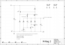
Most recent version of the regulator and JMo3 BOM. Haven't done the BOM for the regulator yet.
Attachments
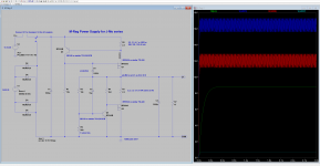
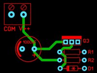
V+ and V++ to electrolytic not optimal, would change routing.
JPhttp://www.dict.cc/englisch-deutsch/criticize.html
JPhttp://www.dict.cc/englisch-deutsch/criticize.html
Unless I'm misreading what you are suggesting, I don't see the need as the output of the circuit is not DC coupled.
I refer at the input. To place a cap in the input to prevent from a non DC free input, to move the bias of both transistors to distortion, or unsafe point (outside SOA).
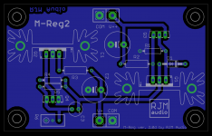
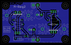
Took the opportunity to clean up the layout a little and reroute some of the traces.
- putting BJTs on the heatsink with the MOSFET would just heat up the BJT needlessly.
- @OdB re. the input coupling cap, I see what you are getting at now. Noted: turning up the volume control with more than a few hundred mV offset on the input will cause the circuit to overheat.
- putting BJTs on the heatsink with the MOSFET would just heat up the BJT needlessly.
- @OdB re. the input coupling cap, I see what you are getting at now. Noted: turning up the volume control with more than a few hundred mV offset on the input will cause the circuit to overheat.
Attachments
@ammel68
If you don't use isolation pads when connecting the MOSFET to the heatsinks, the potential of the heatsink will be the same as the MOSFET substrate. That's a safety risk, though the voltages are in this instance not particularly high. Let's say you slip up with a screwdriver and short the heatsink to the case, such action would be likely to blow the MOSFET.
So that's the argument for grounding the heatsinks: it forces you to use isolating pads and the heatsinks are safely at zero volts.
The argument against says, well, why not just treat them the same as clip-on heatsinks - just with two screws holding them physically in place on the board. Worst case one of them has around 20 V on it, just be reasonably careful to short it to anything.
I'm screwed either way of course: if connected to ground someone will connect the MOSFETs with no isolation and they will immediately blow on power up. If I leave them isolated someone will still connect the MOSFETs with no isolation and manage to short the heatsink to ground and blow the transistors.
My gut feeling is to ground them though, so I can clearly say "USE ISOLATION PADS" and get the pain over with up front.
Richard, thanks for the explanation.
I see now why insulating pads are the safest option.
I don't slip with metal tools and short out devices on heatsinks, but then again most of my projects never make it any type of metal enclosure.
When designing a board to sell, I can see taking the "safest" route since accidents(that slip of the screwdriver) can happen.
V+ or V++ goes first to electrolytic (avoiding T-routing cause etching problems) then to R and Q.
JP
I've noticed several of Richard's boards containing 90 degree(or T-routing as JP calls it) trace intersections.
"T-routing" will obviously work and hasn't been a problem with any commercial board houses that I've used, but having traces intersect at 90 degree angles in general isn't considered to be good layout practice.
Not sure what you mean by it causing etching problems unless you're doing homemade boards.
Now...let's bust out the moonshine and Eagle and get this regulator board done!
Attachments
Um... your regulator board.... naw forget it no comment.
LOL...I was only trying to show JP's suggestion about routing V++ to the cap first in case you didn't understand what he was talking about.
I could easily lay this simple PS board out using yours as a guide while eliminating all of the 90 degree trace intersections on yours, but single supply boards just don't interest me.
So far I'm more than tickled with the SQ of the Jung/Didden Super Regulators I just completed.
Now...let's bust out the moonshine(maybe the sake for Richard since he's in Japan) and Eagle and get these boards done taking into consideration JP's comments/suggestions.

LOL...I was only trying to show JP's suggestion about routing V++ to the cap first in case you didn't understand what he was talking about.
Ah... I'm still a little mystified by this 90 degree business though. I know that for radio frequencies to avoid reflections 45 degree or curved traces are desirable, so is this just an extension to those design rules to audio, or is the "T" thing more a concern about the connection order of the components?
I could easily lay this simple PS board out using yours as a guide while eliminating all of the 90 degree trace intersections on yours, but single supply boards just don't interest me.
Perhaps this might make an interesting comparison against the Jung super-regs.
- Home
- Amplifiers
- Headphone Systems
- JFET-MOSFET headphone amplifier J-Mo 3