Hey there,
I'm stuck with a Beyerdynamic A1 clone kit I'm building: 2015 Latest Headphone Amplifier kit reference to Beyer dynamic A amp | eBay
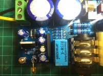
The board is fully populated, and I've applied power:
+/-16vac has been applied to the board from a 30VA centre tapped transformer.
Both LEDs near the driver transistors come on, but the relay does not engage and the front LED does not come on.
If I apply signal and turn up the potentiometer, the heatsinks start getting a bit warm, but no where near hot.
I've attached photos.
If anyone could help me with troubleshooting steps that would be appreciated!
Thanks,
Chris
I'm stuck with a Beyerdynamic A1 clone kit I'm building: 2015 Latest Headphone Amplifier kit reference to Beyer dynamic A amp | eBay
The board is fully populated, and I've applied power:
+/-16vac has been applied to the board from a 30VA centre tapped transformer.
Both LEDs near the driver transistors come on, but the relay does not engage and the front LED does not come on.
If I apply signal and turn up the potentiometer, the heatsinks start getting a bit warm, but no where near hot.
I've attached photos.
If anyone could help me with troubleshooting steps that would be appreciated!
Thanks,
Chris
Attachments
I can report the following:
There is ~11.5vdc across pins 2 (gnd) and 3 (output) on the L7812.
There is ~6.5vdc across pins 5 (gnd) and 8 (vcc) on the UPC1237... which I don't think is enough power looking here: http://www.unisonic.com.tw/datasheet/UPC1237.pdf
There is ~11.5vdc across pins 2 (gnd) and 3 (output) on the L7812.
There is ~6.5vdc across pins 5 (gnd) and 8 (vcc) on the UPC1237... which I don't think is enough power looking here: http://www.unisonic.com.tw/datasheet/UPC1237.pdf
You need to check to see if the it's the amp not working or is it the relay does not make contact. Do you hear a slight click in the headphone that is not working when the relay engages? Connect a source an okay music. Use a DVM in AC volts and probe the input to opamp - is it getting signal (maybe 50mV fluctuating). Then probe opamp output is there signal? There should be some gain higher level. Now probe the output of the power transistors - is there signal? Are the power transistors getting supply current?
Thanks for the reply xrk971!
So I'm looking at this: http://www.ti.com/lit/ds/symlink/mc33078.pdf
Looks like the MC33078 is a dual opamp, and I'm not exactly sure what I should be measuring given there's one per channel.
1. Should I be measuring the inputs with the opamp disconnected?
2. Which pins are the input signal?
3. Which pins are the output signal?
What I can confirm is that each opamp is receiving +-15vdc. Measurement across pin 4 and 8 is ~30vdc. Measurement from either 4 or 8 to pin 2 is 15vdc.
I also have no idea how to measure the driver transistors, which are BD140 and BD139 pairs.
Thanks for all the guidance!
Chris
You will need to find a schematic of the circuit if you want to debug his beyond basics like is the power on, are the connections secure, is the relay working, are the capacitors in the right orientation (backwards electrolytics will pull whole side down). Study the data sheet for opamp find pin corresponding to + - input and output. In BD139/140 they are probably complementary push pull. Find the two pins between 139/140 in common. That's the output.
Thanks xrk971! Turns out the problem was a dodgy 3.5mm jack used as the input... circuit was otherwise perfect.
Got sweet sound out of it now.
There's a minor noise issue I need to sort next. At the moment the circuit ground/transformer centre tap is floating. I haven't connected it to AC ground yet. I'm hoping doing this will help the noise issue.
Got sweet sound out of it now.
There's a minor noise issue I need to sort next. At the moment the circuit ground/transformer centre tap is floating. I haven't connected it to AC ground yet. I'm hoping doing this will help the noise issue.
Glad you found the issue - like Inwas saying - check for obvious causes like a bad connection on input and output.
For your noise issue. I assume you have hum that is audible. It might be worth reading through suggestions people gave me on how to connect earth ground and circuit ground vs circuit clean ground. There are places you don't want to connect the center tap of the transformer. Usually the center tap on secondaries should not be connected earth ground directly. Need a ground loop breaker (GLB). Read this thread - very helpful tips.
http://www.diyaudio.com/forums/power-supplies/306411-strange-forest-noise-linear-psu.html
Hello again!
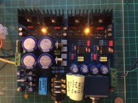
Update on this project: I've installed the PCB into an enclosure alongside its transformer, but I still have noise... Pictures attached.
- It's definitely stronger in the left channel.
- The PCB has a grounding tab that I have not yet soldered. This is connected to the PCB ground, i.e. CT after rectifier and main power caps.
- Currently the PCB is floating. If I bridge the PCB tab and couple it to chassis ground, which is connected to AC Earth, there's no audible difference.
Now I know xrk971 suggested a ground-loop-breaker between the PCB and earth ground, but given there's no audible difference without the GLB, might that point to another problem?
Possible solutions I have on my list:
1. Swap opamps to see if there's a difference across channels
2. Add GLB between PCB and earth ground
3. Buy a new, shielded toroidal
Any input and/or suggestions would be appreciated!
Last edited:
I recently built one of these A1 clone kits and it sounds really good to my ears. I do also have some slight mains hum in both channels, but only when used with my Sennheiser HD590(120ohm) headphones. I imagine the noise-floor increases greatly with 64ohm or 32ohm headphones. When used with my primary set, Beyer DT880 Pro's(250ohms), or my AKG K240DF's(600ohm), I get no hum in either channel and the amp is quiet. The amp absolutely shines with the DT880's and they sound so good they're addictive to listen to, but seems hit or miss with other sets, so I would recommend this build only if you have Beyerdynamic headphones or possibly other high impedance phones. My 600ohm AKG's sound good too, but those are tough to power and I have to dial the amp up to 75% on the volume dial to get a good level out of them.
The only issue I have run into with the higher impedance headphones is some sort of slight low-level digital or computer sounding noise in the right channel that is very infrequent and lasts for a few seconds. It happens maybe once an hour max if it happens at all and could be some sort of EMF interference, maybe from my wifi router which is about 5ft away. I do have a power conditioner that I was going to try plugging the amp into, but really the noise is so slight and rare that I haven't gotten around to doing so.
My build looks pretty similar to the OP's and it looks like we used the same transformer too. The only real difference I can see is that I did use two separate shielded 22awg 2-conductor cables to wire up the jacks for each channel and then shorted ground and low together at both ends, so maybe that helped with noise interference. I grounded my circuit board to earth ground too. Also the Hammond case I used for my build afforded a little more distance between the toroidal transformer and the audio lines which probably helped as well, though I really should have twisted my transformer wiring and done a better job there. Might re-do that in the future.
All in all, I am super happy with this build and, for less than $80 in parts, it sounds great. I have no idea how close the clone sounds to the original A1 nor do I have much of experience in general with high-end heaphone amps, but it does sound much better than my last amp: the SMSL sapII and the built-in one on my Motu 8a audio interface.
- Status
- This old topic is closed. If you want to reopen this topic, contact a moderator using the "Report Post" button.
- Home
- Amplifiers
- Headphone Systems
- Beyerdynamic A1 Clone Troubleshooting