Hello first time poster!
I am attempting to design a very basic EQ for the output of my audio interface's headphone amp. I am using Grado SR125 cans which I enjoy for the most part, but I have decided that they are too bright, and I must build a passive EQ...
The design is 2 simple lowpass shelving filters, which is basically an L-pad with a cap on the shunt. I don't want to use inductors because this is a beginner project for myself, I hope to learn about analog filters in general later.
What is holding up my progress is I do not know how both the headphone and amp impedances will affect the circuit. I also don't have an oscilloscope, I probably need this item yes? I haven't a clue to the impedance of the amp itself. The headphones impedance (according to the test graph on headphone.com) is around 28 with a small bell at 90hz.
The filters are going to be 150hz -6db and something around 1-2khz -3 to -9db, I will attempt to make the upper shelf adjustable.
I am posting this because I need some advice. Is it worth the effort to attempt this project as a beginner, or am I just setting up for failure? It should be kind of obvious I am trying to save some money by using my current amp, although if I could integrate a line level EQ I would.. I'm not sure if my audio interface will accomidate it. Thanks for reading!
The usual DIY headphone "equalizer" is a resistor in series with the output. How this affects the response is dependent on the impedance profile of the cans and of course, the resistor value.
Back in the old days of high impedance (600 ohm) cans, it was expected that there would be a series resistor (120 ohms? I don't remember) on the headphone output circuit. Modern low impedance cans are designed to be driven directly by the headphone amplifier output. Nevertheless, you can affect the response of some with a series resistor. You can get a good idea of how this will affect the response by looking at the impedance vs frequency plot.
If you want to throw a capacitor into the mix, go ahead and try. What do you have to lose? You can make the response like a shelving filter by putting a resistor in series with the capacitor. Try some different component values.
Active line level filter (if used) should be simple. For headphones a "tilt" control often suffices. I think there's even a passive line level tilt control somewhere around here.
I am attempting to design a very basic EQ for the output of my audio interface's headphone amp.
If you have a treble control on your preamp/receiver I'd just use that instead.
The action will be much more predictable. If not, list your equipment and maybe
a better method can be used.
If you have a treble control on your preamp/receiver I'd just use that instead.
The action will be much more predictable. If not, list your equipment and maybe
a better method can be used.
It is an old edirol fa-66 audio interface, with no tone control unfortunately. The amp output is sufficient to be too loud, so using passive shelves wouldn't be a problem.
If you want to try something simple, see how various value series resistors affect the sound. Maybe try several values between 10 - 100 ohms. Carbon or wirewound is OK at these low values. Just use half watt or one watt resistors.
10 ohm, one watt wirewound resistors from Radio Shack hits the sweet spot with my 16 ohm Audio-Technica cans. I don't know what the inductance of these resistors is or if it affects the response. But it works just right.
10 ohm, one watt wirewound resistors from Radio Shack hits the sweet spot with my 16 ohm Audio-Technica cans. I don't know what the inductance of these resistors is or if it affects the response. But it works just right.
It is an old edirol fa-66 audio interface, with no tone control unfortunately.
The amp output is sufficient to be too loud, so using passive shelves wouldn't be a problem.
There may already be series resistors inside to avoid shorting the op amp driver outputs,
but another one in series shouldn't hurt. Try from 10R to 100R. If none of those are quite right,
then you could try adding shunt nonpolar capacitors after the external series resistors.
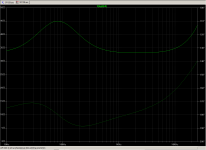
You can trust someone else's measurement, e.g. :
http://www.innerfidelity.com/images/GradoSR125i.pdf
Then you can make up an equivalent circuit, using a combination of L-R-C's.
LT Spice is a useful tool for that.
See for example :
June 2011 : ESP??
Once you achieve that, you can then use LT spice to test the frequency response of your equalisation network.
No measurements required (though still desirable).
Just need to be able to use a simulation tool.
Patrick
no guarantee whether your amp is capable of taking the resulting reactive load.
What would cause this, the capacitor?
So the way I am figuring it now, is that the series resistors will have to be very low, like subohm, to avoid attenuation. If I make the shunt with the appropriate cap and a matching subohm resistor, is this a problem for the amp?
> series resistors will have to be very low, like subohm, to avoid attenuation.
But you said:
> The amp output is sufficient to be too loud
So run it too-loud, attenuate.
No you do NOT need a 'scope. What for?
You want a signal generator and an audio voltmeter.
Or just a matchbook. The amp will probably drive some under 32 Ohms. Your EQ network won't go to zero Ohms. We can start with something a little under 32 Ohms.
Start with a 22 Ohm resistor. Standard value, won't do a lot of attenuation into a 33-44r load, gives a "stopper" so your EQ does not overload the amp.
Another 22r in shunt will reduce level some dB. Series cap in this leg leaves full bass and less in treble. Yes, "an L-pad with a cap on the shunt".
Dartboarding a reactance chart for "bright" suggests 3 or 4 uFd.
Get a bunch of 10 15 22 33 ohm resistors and a bunch of 1uFd caps, non-polar. (Cheap electrolytic will do for tests, before you blow dough for long-life film caps.)
Leave the series leg 22r as it is. Lower may strain the amp, higher just makes more overall loss and more wiggle around the bass resonance. Fiddle the lower 22r and 5uFd to taste.
But in general, the place to EQ is *before* you boost-up to power level. This is still true when "power" is only milliWatts.
Attachments
Member
Joined 2009
Paid Member
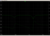
I had some GR60's and gave up on them (sold) for this reason. I didn't try any EQ but rolling off the treble wasn't working - either the sound became too dull r it was too fatigueing. If I were to try again today I'd have a go at some notch filters. Look up details on S. Linkwitz website. He used cap + inductor in series (resonant circuit, impedance becomes lowest at resonance) to shunt the offending spikes in frequency response to ground.
> series resistors will have to be very low, like subohm, to avoid attenuation.
But you said:
> The amp output is sufficient to be too loud
So run it too-loud, attenuate.
No you do NOT need a 'scope. What for?
You want a signal generator and an audio voltmeter.
Or just a matchbook. The amp will probably drive some under 32 Ohms. Your EQ network won't go to zero Ohms. We can start with something a little under 32 Ohms.
Start with a 22 Ohm resistor. Standard value, won't do a lot of attenuation into a 33-44r load, gives a "stopper" so your EQ does not overload the amp.
Another 22r in shunt will reduce level some dB. Series cap in this leg leaves full bass and less in treble. Yes, "an L-pad with a cap on the shunt".
Dartboarding a reactance chart for "bright" suggests 3 or 4 uFd.
Get a bunch of 10 15 22 33 ohm resistors and a bunch of 1uFd caps, non-polar. (Cheap electrolytic will do for tests, before you blow dough for long-life film caps.)
Leave the series leg 22r as it is. Lower may strain the amp, higher just makes more overall loss and more wiggle around the bass resonance. Fiddle the lower 22r and 5uFd to taste.
But in general, the place to EQ is *before* you boost-up to power level. This is still true when "power" is only milliWatts.
I was able to get 6 .22uF 50v metal film caps from a local radioshack yesterday, do you think this is not enough farads?
The goal is also to use 2 or possibly 3 of these circuits (last one being a lowpass) to create the necessary tilt. Maybe the lowpass is unnecessary due to circuity in the cans? To accomidate the extra legs, can I lower the series resistance, or is the problem more complicated then?
Could I use transformers to help avoid these problems?
I am building my perfboard currently, I am going to start with the series resistor as fast eddie suggested, I am guessing the result will be signal attenuation with upwards treble tilt due to voice coil impedance and more resonance at the driver Fn.
I suppose "subohm" resistances are a bad idea because this acts similar to a short circuit?
I appreciate all the help!
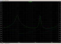
Just for fun.
Please don't copy blindly. Try it out yourself in Spice.
I tried

was using easyeda online and I realized I don't know how to use spice correctly. The simulation results for an AC sweep were crazy.
But I did manage to figure out what the series resistance will do.
After testing the series resistor only, I found (by ear) a -6dB drop with a 77ohm resistance (using multimeter and trimmer), and -3dB with 27ohm. I couldn't tell much about change in frequency response.
Does that mean I get -6dB total attenuation if I use the two "pads with caps" with matching 38ohm resistances?
That would work fine, but I would like less attenuation for those noisy times.
Does that mean I get -6dB total attenuation if I use the two "pads with caps" with matching 38ohm resistances?
That would work fine, but I would like less attenuation for those noisy times.
Last edited:
I already plotted everything out for you in post #15.
Yes but after examining your spice netlist, you had used a completely different filter with inductors as well.
- Status
- This old topic is closed. If you want to reopen this topic, contact a moderator using the "Report Post" button.
- Home
- Amplifiers
- Headphone Systems
- Headphone equalization after amp