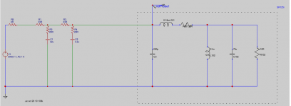
EUVL, thank you for the sr125 schematic. I have come up with this circuit as an acceptable compromise of attenuation.
When I did a simulation into a dummy impedance of 10k, the shunt leg resistance for a -6dB shelf was equal to the series resistance before it. After running the spice sim on your schematic, that resistance had to be lowered.
I am a total beginner at electronics, so I have to ask, what changed between my simulation and yours? Just for education if you have the opportunity.
If this circuit doesn't work, I will come back and bitch and moan about it! haha JK, maybe if it actually do fry anything I will build an amp, as long as my interface still works!
Thanks
When I did a simulation into a dummy impedance of 10k, the shunt leg resistance for a -6dB shelf was equal to the series resistance before it. After running the spice sim on your schematic, that resistance had to be lowered.
I am a total beginner at electronics, so I have to ask, what changed between my simulation and yours? Just for education if you have the opportunity.
If this circuit doesn't work, I will come back and bitch and moan about it!
haha JK, maybe if it actually do fry anything I will build an amp, as long as my interface still works!Thanks
Attachments
> into a dummy impedance of 10k
Are your headphones 10K? Is this a realistic approximation to what you really want?
My Corgi can carry an envelope. He can't carry the NYC phone book.
> shunt leg resistance for a -6dB shelf was equal to the series resistance before it.
For NON-loaded networks (10K is hardly-loading 30-ohm nets), yes R=R gives -6dB.
When you hang 35 Ohms on 22 ohms shunted with 22 ohms, loading is significant, math is more work.
I still think a fistful of parts will get you there faster than teasing the computer or filling matchbooks with figures.
I've been re-doing the spice sim for a few hours, added bleeder resistors (prob not necessary but IDK with the huge caps) and matched my gain drop figures to find that the first series resistor (simulating amp impedance?) is approx 33ohm. I added a fixed 33 resistor after the caps and a pot for the filters series resistances. Unfortunately I'll have to wait to order the right caps bbecause the last radioshack in my town didn't have what I needed
Member
Joined 2009
Paid Member
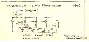
Here's a picture of what I was describing above. I suspect that you won't get the results you want without trying something along these lines.
Link here: Reference earphones
And some other interesting work: How to equalize your headphones: A Tutorial
Tempts me to try a pair of headphones again.
Link here: Reference earphones
And some other interesting work: How to equalize your headphones: A Tutorial
Tempts me to try a pair of headphones again.
Attachments
I while back I created a software EQ curve for my Grado SR80Es. It made them much more listenable, but I eventually switched to different cans. I miss the insane speed of the Grado transducers, but not their peaky treble.
It's nice to try to simulate and fix this, but the best EQ for Grados is to throw them in the trash. Horrid things.
Would it be worthwhile to try a crossover simulator like XSim?
I tested the frequency response changes in a DAW digitally, before planning the circuit. The result was a more natural feeling of bass vs treble, without the fatigue, and still plenty audible details. In fact it was confusing, going back to my speaker monitors after making some synth sounds, the monitors couldn't compare the amount of bass impact at the ear, and the mids were leveled in almost perfect. Although the hype of the grados around 8khz was still there, but sounded much better compared to my monitors.
Gads, I knew something was different when I used this technique with my tube power amp and planar headphones. I built a little voltage divider, using 33 ohm in series and 10 ohm shunt to ground. On one hand, it did take care of the hum problem that was due to the amp itself plus the high sensitivity of the HE400S phones. But there was something about the midbass. Different, maybe thicker. I realize that there will be numerous possibilities because of the relationship between the voltage divider, amp and chosen set of phones. For example, Grado 225e phones sound much brighter with this arrangement, and that is something I don't need. The planars react more towards what I like to hear, but I'm afraid that I cannot comment on the technical reasons for this since, I am more of a parts changer than a tech. These are just my observations. FWIW, both phones are 22 ohm impedance, and relatively high sensitivity i.e. 96-98db
I put this project on hold, many things are difficult for me about it.
Finding 2-gang pots or trimmers in the right range is impossible. Least maximum devices I found were 1k ohm, and while I could use a parallel resistor to lower that, I think the attenuation curve would be wrong, possibly making it difficult to tune by hand.
I thought about using an IC socket to plug caps into, since a variable cap isn't available, and the right size caps for this aren't plentiful, and they are expensive, around 5 dollars a unit and I would need a lot of them to tweak the capacitance.
Trying to simulate the actual stereo circuit I ran into problems also. Could be my lack of electronics skill, but the program I was using didn't help either. For some reason I can't run LTSpice on my computer, crashes on startup.
If it's possible to use electrolytic caps I think I would, film caps are pretty expensive for the size required.
Although I am reconsidering using caps totally, but where do I find the proper inductors? I am slightly concerned about them picking up stray hum.
Rather than putting a passive equalizer on the output of the amplifier; which will likely change or corrupt the audio quality. Design and put a very clean 3 or 4 band parametric EQ on the input of the amplifier. I have a very high quality h.a. w separate isolated power supplies. It drives a highly modified pair of Fostex T50RP Orthodynamic phones. The 8khz peak is taken down using 2mm thick felt over the drivers. Low end rolloff is flattened by the equalizer as is the low mid dip & the hi freq. roll off. The result is a nearly flat response h.p.; that turns a fair sounding set of phones into a great sounding one.
The EQ controls are only +- 4db & the frequencies to be compensated are arrived at by measuring the drivers on a calibration rig; then correcting the areas in the frequency response, to give flat response approx. +- 3db over the bandwidth 25hz to 20khz. I used LME49860 dual opamps in the filter; unfortunately T.I. stopped manufacture of this National chip 2 yrs. ago.
The EQ controls are only +- 4db & the frequencies to be compensated are arrived at by measuring the drivers on a calibration rig; then correcting the areas in the frequency response, to give flat response approx. +- 3db over the bandwidth 25hz to 20khz. I used LME49860 dual opamps in the filter; unfortunately T.I. stopped manufacture of this National chip 2 yrs. ago.
ANY equalisation throws away voltage headroom (including our own Danyuk cross-feed filter).
You can of course regain the loss by adding extra gain in your chain (e.g. at the EQ filter).
But that is the same as adding gain elsewhere in the chain.
A passive EQ after the amp means of course the amp has to work harder, with higher output voltages.
That normally also means higher distortion, and energy consumption especially in Class A.
Which is why it is usually better to do it at line level.
DSP EQ reminds me of smartphone cameras.
They have really lousy optics.
But the CMOS imaging chip has enough resolution that you can do software correction.
So after correction it is so good that it satisfies 99.9% of the users.
Unless you are a pro.
Then you will always insists on Zeiss lenses.
Patrick
- Status
- This old topic is closed. If you want to reopen this topic, contact a moderator using the "Report Post" button.
- Home
- Amplifiers
- Headphone Systems
- Headphone equalization after amp