Hello All,
At first I wasn’t sure about where to post this thread. The end result will be a tube headphone amplifier. So here we are in the tube section.
For years most of the things I have built are headphone amplifiers. Lately even a couple solid state. For measured noise, distortion and dampening you cannot beat SS. However I cannot stay away from tubes. I have tried a lot of different tubes and output transformers; Sowter, Edcor, Transendar and now Lundahl LL6989 (18mA)
I started this adventure with no test instruments. I would put the cans on my head and go to it. I came to the observation that I do not like hum and or buzz. Several months ago I got a used Audio Precision System Two Analyzer. It became clearly evident that increasing tube amplifier output impedance has a large influence on distortion, frequency response and phase performance of headphones with a pronounced impedance / resonance peak. I use and like Sennheiser HD-600’s.
I got to looking around at the headphone test results posted at innerfadility.com and came across the Audeze LCD2 with Fazer. The LCD2 has a ruler flat impedance curve, without a hint of resonance or phase shift. The LCD2’s are a purely resistive load.
Now to the tube amplifier: I have a mono version on the bench conenected to the AP analyzer.
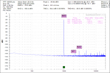
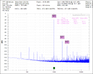
Using a 12B4A and Lundahl LL6989 (18mA) transformer; The transformer primaries are connected in parallel with -17.5gV and 34mA and an signal input voltage of 0.200V the output voltage across 72R ohms is 0.114V. Per the InnerFidelity test results 0.114V produces 90dB’s at the test head ear microphone. 2 volts input will produce more than 110dB at the test head ear microphone.
See the attached FFT. At 90db there is 0.45% THD+Noise
Thoughts Comments?
DT
At first I wasn’t sure about where to post this thread. The end result will be a tube headphone amplifier. So here we are in the tube section.
For years most of the things I have built are headphone amplifiers. Lately even a couple solid state. For measured noise, distortion and dampening you cannot beat SS. However I cannot stay away from tubes. I have tried a lot of different tubes and output transformers; Sowter, Edcor, Transendar and now Lundahl LL6989 (18mA)
I started this adventure with no test instruments. I would put the cans on my head and go to it. I came to the observation that I do not like hum and or buzz. Several months ago I got a used Audio Precision System Two Analyzer. It became clearly evident that increasing tube amplifier output impedance has a large influence on distortion, frequency response and phase performance of headphones with a pronounced impedance / resonance peak. I use and like Sennheiser HD-600’s.
I got to looking around at the headphone test results posted at innerfadility.com and came across the Audeze LCD2 with Fazer. The LCD2 has a ruler flat impedance curve, without a hint of resonance or phase shift. The LCD2’s are a purely resistive load.
Now to the tube amplifier: I have a mono version on the bench conenected to the AP analyzer.
Using a 12B4A and Lundahl LL6989 (18mA) transformer; The transformer primaries are connected in parallel with -17.5gV and 34mA and an signal input voltage of 0.200V the output voltage across 72R ohms is 0.114V. Per the InnerFidelity test results 0.114V produces 90dB’s at the test head ear microphone. 2 volts input will produce more than 110dB at the test head ear microphone.
See the attached FFT. At 90db there is 0.45% THD+Noise
Thoughts Comments?
DT
Attachments
")

Maybe I should just say OP's measurement looks just like a simple two FET portable amp's harmonic profile and leave off the link to the portable amp and reference to the low cost of equipment needed to almost do what an AP system can do.
The data should be ok to show though right?
The data should be ok to show though right?
In a shielded steel can
Nn xrk971,
If we are playing rock paper scissors, I will go off topic with you.
Recall that I said,
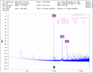
Hear is a pure battery powered LM4562 and LME49600 Headphone amp tested with a battery powered laptop and QA401 audio analyzer FFT scan.
The voltage output is the same as the previous tube FFT scan.
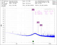
Now back on topic see the attached 12B4A tube plot done with the bread board in a shielded can.
DT
Nn xrk971,
If we are playing rock paper scissors, I will go off topic with you.
Recall that I said,
Hello All,
... For measured noise, distortion and dampening you cannot beat SS. However I cannot stay away from tubes.....
DT
Hear is a pure battery powered LM4562 and LME49600 Headphone amp tested with a battery powered laptop and QA401 audio analyzer FFT scan.
The voltage output is the same as the previous tube FFT scan.
Now back on topic see the attached 12B4A tube plot done with the bread board in a shielded can.
DT
Attachments
Nn xrk971,
If we are playing rock paper scissors, I will go off topic with you.
Recall that I said,
Hear is a pure battery powered LM4562 and LME49600 Headphone amp tested with a battery powered laptop and QA401 audio analyzer FFT scan.
The voltage output is the same as the previous tube FFT scan.
Now back on topic see the attached 12B4A tube plot done with the bread board in a shielded can.
DT
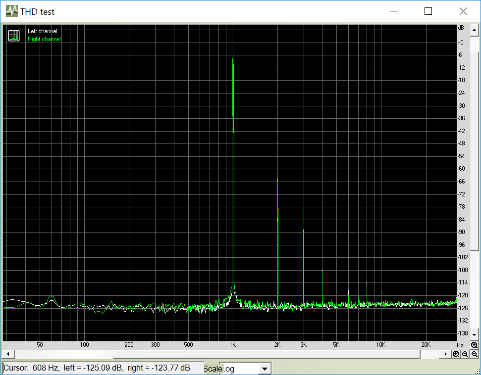
I have a Fiio A5 with Muses02 and LME49600 and it measures very low THD as well. But it doesn't sound better! Not even close and many agree as can be seen in results of poll from virtual blind audition thread. I think if you look at that plot you see that H3 is higher than H2 - very unnatural sounding. H2 should be highest and it should descend monotonically. Like your tube amp. And like my FET amp.
Sorry to be off topic. I am building a hybrid SE Class A soon - for same reasons you like tubes as well.
Here was plot removed from previous post again to show similarities with your tube amp and the 2 FET SE Class A amp.
Now back to all tube amps.
I use and like Sennheiser HD-600’s.
I got to looking around at the headphone test results posted at innerfadility.com and came across the Audeze LCD2 with Fazer. The LCD2 has a ruler flat impedance curve, without a hint of resonance or phase shift. The LCD2’s are a purely resistive load.
Now to the tube amplifier: I have a mono version on the bench conenected to the AP analyzer.
I also have a pair of HD-600's, I really like the clean and detailed sound -- and they are comfortable to me. Audeze and Hifi Man have extremely good sound, but the fit and comfort was a big factor for me. I was able to try on a variety of headphones at a HeadFi meet in Seattle a few years ago. I would highly recommend trying out your candidates before spending serious money on them.
HelloNn xrk971,
If we are playing rock paper scissors, I will go off topic with you.
Recall that I said,
Hear is a pure battery powered LM4562 and LME49600 Headphone amp tested with a battery powered laptop and QA401 audio analyzer FFT scan.
The voltage output is the same as the previous tube FFT scan.
Now back on topic see the attached 12B4A tube plot done with the bread board in a shielded can.
DT
Very interested in your amps topology. I have a lot of 12B4A and need to put them to good use. Could you please post Sch. or PM it to me.
Thanks
bOTL
Maybe I should just say OP's measurement looks just like a simple two FET portable amp's harmonic profile and leave off the link to the portable amp and reference to the low cost of equipment needed to almost do what an AP system can do.
The data should be ok to show though right?
Can you stop advertising your amp in every single thread here? I feel so annoying!
Can you stop advertising your amp in every single thread here? I feel so annoying!
Proid,
Relax man, really wasn't an advert - just pointing pointing out similarities in the FFT's. I am agreeing with the OP that his amp sounds great based on the harmonic profile. It would be good if we could see the schematic. I am guessing it is single ended class A. That's all. Be annoyed if you must.
Damping ratio does not matter so much
Hello,
Still looking at the design goals, this is a beginning of a list:
Tube amplifier where output impedance is less important as this amplifier is intended to work with headphones with flat impedance curves. The turn ratio of the output transformer will:
Minimize noise at comfortable listening level
Low distortion at comfortable listening level
Ample headroom (but not too much) at 2 volts input
Plus
Plus
The current configuration is a 12B4A Single End Triode (common cathode) with a bypassed cathode resistor. The output transformer is a Lundahl LL1689 18mA with the primary windings in parallel making a turn ratio of 9:1. This is not a one size fits all design. You can think of it as starting with the 72 ohm Audeze LCD 2 Fasor working into the LL1689 transformer and the transformer matching the flat Audeze impedance curve with the rp of the 12B4A triode.
Damping ratio does not matter so much
The operating point is straight from the data sheet. Plate voltage ~150 V, grid voltage -17.5V, 0.035mA and cathode resistor is 500 Ohms. All Powered with bench variable power supplies
More later.
DT
http://www.mif.pg.gda.pl/homepages/frank/sheets/093/1/12B4A.pdf
Hello
Very interested in your amps topology. I have a lot of 12B4A and need to put them to good use. Could you please post Sch. or PM it to me.
Thanks
bOTL
Hello,
Still looking at the design goals, this is a beginning of a list:
Tube amplifier where output impedance is less important as this amplifier is intended to work with headphones with flat impedance curves. The turn ratio of the output transformer will:
Minimize noise at comfortable listening level
Low distortion at comfortable listening level
Ample headroom (but not too much) at 2 volts input
Plus
Plus
The current configuration is a 12B4A Single End Triode (common cathode) with a bypassed cathode resistor. The output transformer is a Lundahl LL1689 18mA with the primary windings in parallel making a turn ratio of 9:1. This is not a one size fits all design. You can think of it as starting with the 72 ohm Audeze LCD 2 Fasor working into the LL1689 transformer and the transformer matching the flat Audeze impedance curve with the rp of the 12B4A triode.
Damping ratio does not matter so much
The operating point is straight from the data sheet. Plate voltage ~150 V, grid voltage -17.5V, 0.035mA and cathode resistor is 500 Ohms. All Powered with bench variable power supplies
More later.
DT
http://www.mif.pg.gda.pl/homepages/frank/sheets/093/1/12B4A.pdf
Test drive power supply.
Hello All,
I have been playing with this a bit more to build a prototype to listen to.
First off is a power supply to make this thing percolate. I need 186 VDC at 0.035 A input I had a name brand kit series voltage regulator in a box near my bench. This regulator holds a LM350 (LM317 type device) voltage regulator and an IXCP 10M45S as a pass device. You can read about these devices used together as regulators here
http://waltjung.org/PDFs/Sources_101_P2.pdf.
Not knowing what voltage transformer would best work with this voltage regulator kit I connected the bench DC power supply directly to the IXCP 10M45S input pin thinking that knowing what filtered DV voltage would work best I could select a transformer to work with the kits’ bridge rectifier and filter capacitor input later.
I connected everything together and swept the input DC voltage from 0VDC to about 260VDC. With my DVM and audio analyzer I found that the regulator kit regulated the output voltage at an input voltage just a few volts above the set point. However the FFT revealed an unfortunate hump in the noise floor centering around 1300 Hz. As I swept the input voltage up to above 250VDC the unfortunate hump in the noise floor disappeared and the SNR improved by about 5dB.
I am thinking that there may be some instability due to the small voltage margin between the pass device and the regulator. Even though the LM350 is a low drop out voltage device there is limited voltage margin between the LM350 and 10M45S to work within.
See the attached FFT’s
The voltage regulator kit worked best with nearly 60 volts dropped between the input and the output. 60 volts times 0.040 A, equals 2.4 watts dissipated in the kit’s heatsink. That is a lot of heat! So I am thinking that with that much dissipated heat why not use a shunt regulator? I have ordered two of these shunt regulators to test drive.
http://kandkaudio.com/images/Shunt_Regulator_100-350V_Rev_3.doc.
DT
Attachments
Hello All,
The shunt regulator kits have arrived from K&K Audio. One is assembled. Before connecting, adjusting and testing, I thought to test this 12B4A headphone concept with no voltage regulator. Seems that 0.111V RMS output load should not be a demanding load to drive.
With the series regulator removed and additional R-C filter steps added to increment the B+ voltage down to 160VDC, I ran another FFT plot. Overall Distortion and Noise only changed a little. The 120hz bridge rectifier effect and harmonic series is a more pronounced. The most remarkable thing is the noise floor on the low frequency end of the scale is reduced by ~15dB.
What I thought to be tube 1/f noise in the original FFT plots may actually be added frequency noise from the series regulator.
In a couple of days I will place the shunt regulator into the mix and post a FFT plot of the results.
DT
Attachments
Last edited:
I am beginning to prefer this shunt regulator
Hello All,
The shunt regulator kit from K&K Audio is adjusted to a constant total of 0.060A the 12B4A with a 500 OHM cathode resistor has the grid voltage adjusted to -17.5V the resulting current through the 12B4A is very near 35ma. The current through the shunt at idle is very near 25ma.
The typical current through the shunt is set to two times the current swing through the load. If we were looking at a current swing of ~35 ma through the 12B4A, the current through the shunt would be set to 70ma. Remember for this headphone amplifier the output is designed to be much less that the possible absolute maximum current swing, less than 1ma. 25ma through the shunt is huge by comparison.
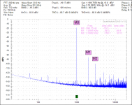
The headphone amplifier % distortion is proportional to possible output. Today's measured amplifier distortion + Noise is 0.043% at a simulated 90dB’s inside the headphones. 0.111V
Today I connected the Keysight N5752A bench DC supply to the K&K Shunt regulator input and adjusted the voltage until the meter showed a constant 0.060A, then adjusted the voltage into the regulator up another ~ 20V to 212VDC.
See the attached FFT plot.
That 60hZ spike showed up prior to switching on either the heater power supply or high voltage power supply. I think that it is related to the utility transformer between my house and the neighbor’s. Early in the small hours of the morning that spike is much smaller. I will continue to chase the 60hZ culprit.
I am beginning to prefer this shunt regulator to no regulator and the Broskie series regulator. The amplifier's Signal to Noise Ratio with the shunt regulator is improved by several dB’s over both other options. The series regulator has a marked increase in frequency (1/F) noise over either no regulator or the shunt regulator.
DT
Hello All,
The shunt regulator kit from K&K Audio is adjusted to a constant total of 0.060A the 12B4A with a 500 OHM cathode resistor has the grid voltage adjusted to -17.5V the resulting current through the 12B4A is very near 35ma. The current through the shunt at idle is very near 25ma.
The typical current through the shunt is set to two times the current swing through the load. If we were looking at a current swing of ~35 ma through the 12B4A, the current through the shunt would be set to 70ma. Remember for this headphone amplifier the output is designed to be much less that the possible absolute maximum current swing, less than 1ma. 25ma through the shunt is huge by comparison.
The headphone amplifier % distortion is proportional to possible output. Today's measured amplifier distortion + Noise is 0.043% at a simulated 90dB’s inside the headphones. 0.111V
Today I connected the Keysight N5752A bench DC supply to the K&K Shunt regulator input and adjusted the voltage until the meter showed a constant 0.060A, then adjusted the voltage into the regulator up another ~ 20V to 212VDC.
See the attached FFT plot.
That 60hZ spike showed up prior to switching on either the heater power supply or high voltage power supply. I think that it is related to the utility transformer between my house and the neighbor’s. Early in the small hours of the morning that spike is much smaller. I will continue to chase the 60hZ culprit.
I am beginning to prefer this shunt regulator to no regulator and the Broskie series regulator. The amplifier's Signal to Noise Ratio with the shunt regulator is improved by several dB’s over both other options. The series regulator has a marked increase in frequency (1/F) noise over either no regulator or the shunt regulator.
DT
Attachments
- Status
- This old topic is closed. If you want to reopen this topic, contact a moderator using the "Report Post" button.
- Home
- Amplifiers
- Headphone Systems
- A tube headphone amplifier