Hi Forum, new member here ") Yesterday I built my first headphone amp and wanted to share it with you. It is basically the "textbook" cmoy topology from the tangentsoft website.
Yesterday I built my first headphone amp and wanted to share it with you. It is basically the "textbook" cmoy topology from the tangentsoft website.
All parts are scrapped from my fathers various "old parts bins" (he is a electronics engineer) while I visited my parents yesterday. Soldered with my newly built Hakko T12 clone. I am a bit out of practice since I left for studying 10 years ago, so yeah, that's not a perfect soldering job. But as you see, I am working on it [and I think I prefer sticking things on PCBs and putting them into the reflow oven; too bad my father sold that one!]
About the amp:
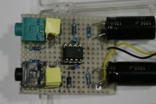
The power supply is a simple voltage divider with 4.7k resistors and 1000uF/50V caps. A bit big and I could have gone for 470uF/16V, but wanted to be on the safe side. Also, these look nicer
Input voltage is 24V DC (random wall wart), and the rails are at +/-12V +/- 50mV each.
On the input side (green connector) I decided to leave out the volume poti, since I couldn't find a stereo poti. Instead, the input ground is connected directly to the virtual ground, and the level is reduced by a 4.7k input resistor.
Input DC goes through a low pass with 4x220nF and 100kR, giving -3dB cut-off at 1.8Hz (which is a bit low, seems I got an error when I first calculated that to be about 6 or 12Hz). The quad-capacitor design is because I had about 30 of those, a single, HUGE, wima cap (about the size of a 9V block battery) and a random assortment of different sizes PPs.
The gain is set via 10k and 4.7k to about 3.2. Driving my HD650s that's still a bit too much, but so I might go down a gain of 1.5.
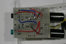
Grounding scheme is quite simple: One ground point per channel at opposite sides of the board (about mid), connected to a common ground point between the voltage divider. The input and output grounds are all connected to the same blob of solder.
For the op amp, I tried a few various types my father had lying around from old projects. The RC4558 did produce a lot of DC, which we couldn't reduce to sane levels (about 170mV!) with the proto board setup. Not sure if that was due to the old IC, bad design, or just a problem with the RC4558...
I settled with the MC1458, which is at about 5mV DC. I usually drive the HD650s with 1V peak-to-peak.
Measured the whole thing with a Tektronix digital oscilloscope into a dummy load of about 300 Ohms. Dummy load because I hate being in the same room when doing chirps, and I also didn't want to accidentally fry new headphones ;-) Yeah, I know the difference between normal [what's the English word] and complex loads.
As source I only had a Samson Go Mic with me, and while doing a chirp from 10Hz to 20kHz (sine) the amplitude stayed at the same level. Crosstalk was nigh immeasurable. I didn't have a proper signal generator or spectroscope, but I believe the Samsons DAC was more limiting than the opamp. Doing a chirp with square signal resulted in "garbage in, garbage out" (plus some gain).
Since the resistors/caps are pair wise selected to match for each channel, there was also no measurable difference in the output.
SQ wise the whole thing sounds pretty good. On the go I use a Sony Z1, which previously had problems delivering enough power to the HD650. At home I have a WM8524 based DAC. For convenience reason, the amp is connected to the tape out of my Pre-Amp (Rotel RSP 960AX), which is basically just a pass-through of the Line-In/DAC.
When I set my full size speakers to roughly the same level as I drive my headphones (Visaton Atlas Mk1 four-way cabinets on a Rotel RB 971), the difference between what I hear with and without the cans becomes very low. (Yes, there is some bleeding, but even without that, i.e. turned of power amp, the difference is astonishing low).
What should I say? I am amazed! Also: No (perceivable) noise.
The only drawbacks are the missing anti-plopp when plugging out the source with the amp on and headphones connected, and volume control. The anti-plopp is the reason this will not stay my final amp: I know this will one day ruin the cans.
Missing VC: On the phone that's okay, since its output level is not that high. But at home, I have to set my DAC in Windows to an output level of 8/100 for normal listening levels. With 24 bit output that should be not an issue (losing about 4 bits of precision edit: blurb, of course the VC is not linear, so it's way more), but I'd rather be on the safe side there.
I am now looking into swapping the MC1458 for a true audio op amp like the NJM4556 or even the OPA1622.
Some data on the MC: designed 1971, 0.5V/uS slew rate at unity gain (10V_in, 2kO R_L, +/-15Vcc), V_IO 7.5mV, 120dB cross talk attenuation, 75 Ohm output resistance, no idea bout output current.
So all in all pretty bad for audio (besides the cross talk), but well - the amp works, and that with an improper op amp for that application!
Oh, and yeah, I am an engineer, but one of those with a software prefix. So building something like this is new for me; I really enjoyed it though.
Of course I am happy if you can give some hints what could be done better (besides the amount of solder in some places).
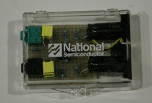
Ah, and I found the enclosure to be "quite a fit". Though the National Semi print is a bit of a lie...
Yesterday I built my first headphone amp and wanted to share it with you. It is basically the "textbook" cmoy topology from the tangentsoft website.All parts are scrapped from my fathers various "old parts bins" (he is a electronics engineer) while I visited my parents yesterday. Soldered with my newly built Hakko T12 clone. I am a bit out of practice since I left for studying 10 years ago, so yeah, that's not a perfect soldering job. But as you see, I am working on it
[and I think I prefer sticking things on PCBs and putting them into the reflow oven; too bad my father sold that one!]About the amp:
The power supply is a simple voltage divider with 4.7k resistors and 1000uF/50V caps. A bit big and I could have gone for 470uF/16V, but wanted to be on the safe side. Also, these look nicer
Input voltage is 24V DC (random wall wart), and the rails are at +/-12V +/- 50mV each.
On the input side (green connector) I decided to leave out the volume poti, since I couldn't find a stereo poti. Instead, the input ground is connected directly to the virtual ground, and the level is reduced by a 4.7k input resistor.
Input DC goes through a low pass with 4x220nF and 100kR, giving -3dB cut-off at 1.8Hz (which is a bit low, seems I got an error when I first calculated that to be about 6 or 12Hz). The quad-capacitor design is because I had about 30 of those, a single, HUGE, wima cap (about the size of a 9V block battery) and a random assortment of different sizes PPs.
The gain is set via 10k and 4.7k to about 3.2. Driving my HD650s that's still a bit too much, but so I might go down a gain of 1.5.
Grounding scheme is quite simple: One ground point per channel at opposite sides of the board (about mid), connected to a common ground point between the voltage divider. The input and output grounds are all connected to the same blob of solder.
For the op amp, I tried a few various types my father had lying around from old projects. The RC4558 did produce a lot of DC, which we couldn't reduce to sane levels (about 170mV!) with the proto board setup. Not sure if that was due to the old IC, bad design, or just a problem with the RC4558...
I settled with the MC1458, which is at about 5mV DC. I usually drive the HD650s with 1V peak-to-peak.
Measured the whole thing with a Tektronix digital oscilloscope into a dummy load of about 300 Ohms. Dummy load because I hate being in the same room when doing chirps, and I also didn't want to accidentally fry new headphones ;-) Yeah, I know the difference between normal [what's the English word] and complex loads.
As source I only had a Samson Go Mic with me, and while doing a chirp from 10Hz to 20kHz (sine) the amplitude stayed at the same level. Crosstalk was nigh immeasurable. I didn't have a proper signal generator or spectroscope, but I believe the Samsons DAC was more limiting than the opamp. Doing a chirp with square signal resulted in "garbage in, garbage out" (plus some gain).
Since the resistors/caps are pair wise selected to match for each channel, there was also no measurable difference in the output.
SQ wise the whole thing sounds pretty good. On the go I use a Sony Z1, which previously had problems delivering enough power to the HD650. At home I have a WM8524 based DAC. For convenience reason, the amp is connected to the tape out of my Pre-Amp (Rotel RSP 960AX), which is basically just a pass-through of the Line-In/DAC.
When I set my full size speakers to roughly the same level as I drive my headphones (Visaton Atlas Mk1 four-way cabinets on a Rotel RB 971), the difference between what I hear with and without the cans becomes very low. (Yes, there is some bleeding, but even without that, i.e. turned of power amp, the difference is astonishing low).
What should I say? I am amazed! Also: No (perceivable) noise.
The only drawbacks are the missing anti-plopp when plugging out the source with the amp on and headphones connected, and volume control. The anti-plopp is the reason this will not stay my final amp: I know this will one day ruin the cans.
Missing VC: On the phone that's okay, since its output level is not that high. But at home, I have to set my DAC in Windows to an output level of 8/100 for normal listening levels. With 24 bit output that should be not an issue (losing about 4 bits of precision edit: blurb, of course the VC is not linear, so it's way more), but I'd rather be on the safe side there.
I am now looking into swapping the MC1458 for a true audio op amp like the NJM4556 or even the OPA1622.
Some data on the MC: designed 1971, 0.5V/uS slew rate at unity gain (10V_in, 2kO R_L, +/-15Vcc), V_IO 7.5mV, 120dB cross talk attenuation, 75 Ohm output resistance, no idea bout output current.
So all in all pretty bad for audio (besides the cross talk), but well - the amp works, and that with an improper op amp for that application!
Oh, and yeah, I am an engineer, but one of those with a software prefix. So building something like this is new for me; I really enjoyed it though.
Of course I am happy if you can give some hints what could be done better (besides the amount of solder in some places
).Ah, and I found the enclosure to be "quite a fit". Though the National Semi print is a bit of a lie...
Attachments
Last edited:
Welcome to diyAudio
Nothing beats get sound out of a first build... well done Hard to say why the 4558 had such a poor offset... it sounds a bit like something else was going on tbh. I see you have a scope and so you should be able to tell if it was oscillating (unstable). Dunno You would have to try another device to prove it one way or the other. The 4556 is good for current delivery while FET input devices should all come out at virtually zero offset.
Thinking about it (haven't got the CMOY details in front of me), 170mv may not be out of the way if you have DC coupled the feedback return and are running hugely differing impedances on each of the two opamp inputs.
Nothing beats get sound out of a first build... well done
Hard to say why the 4558 had such a poor offset... it sounds a bit like something else was going on tbh. I see you have a scope and so you should be able to tell if it was oscillating (unstable). Dunno You would have to try another device to prove it one way or the other. The 4556 is good for current delivery while FET input devices should all come out at virtually zero offset. Thinking about it (haven't got the CMOY details in front of me), 170mv may not be out of the way if you have DC coupled the feedback return and are running hugely differing impedances on each of the two opamp inputs.
> 170mv may not be out of the way if you have DC coupled the feedback return and are running... ...
Yeah, back on Cmoy's forum we traced large DC offset to some interaction between load, +In bias R, NFB, and the rail-splitter. The forum is gone, as is my memory. But IIRC tenths-volt WAS to be expected in some worst-cases.
AH! Tangent saved the analysis. Go here, go down to "Resistor Divider", see 2nd diagram in that section and accompanying text. A good opamp's 1mV offset is multiplied to 11mV across the load, not a hige deal. (Old '4558 had 5mV offset so 55mV on load.) (Further error due to '4558's bias current in 100K.) However the load to the splitter multiplies this again and can force the "ground" WAY off half-voltage.
"...a 9 V battery would split to about +3.7 V and -5.3 V instead of the ideal ±4.5 V"- YMMV.
__________________________
True RC4558 should be sold on a fuzz-pedal DIY forum, they like em. They are undistinctive below clipping but I assume their overload action is more euphonic than many "better" chips. Also the inputs will work very-very close to the negative rail which means some sidechain "DC" processing can be done near 0V instead of biased-up mid-supply.
That analysis up looks good! Could be the reason the RC missbehaved.
Too bad the digital oscilloscope is at my parents place, and for the old, analog I don't have enough space in my university dorm room But that will change later this year...
But good thing that reducing the gain should also reduce the DC offset.
Also I noticed the input impedance is not "as suggested in the cmoy design", since I don't have a 10k voltage divider/VC between input + and virtual GND. Instead, I feed the signal into the op amp with a 4.7k series resistor (on +), and the low pass with a 100k resistor.
So on DC, my DAC sees about 104.7k and on AC... well, no idea. On a perfect op-amp in non-inverting configuration it should be about infinity, but reality is probably different (can't measure before I am returning from vacation).
Today I designed a small OPA1622 to DIP-8 break out in Eagle (with a close-to-minimal footprint) to put that chip in my Cmoy. But panelized to 10x10cm and with a MOQ of 10 boards, these would easily become >500 breakouts in one order. Maybe I can get it down to about 100 for the cheapest dirtypcb offer. Will post if anyone is interested ;-)
Hm, designing a proper preamp with DAC + Headphone becomes very interesting now that I started to work with PCB layouting I should read up on that and convince TI to send my employer some samples...
Too bad the digital oscilloscope is at my parents place, and for the old, analog I don't have enough space in my university dorm room
But that will change later this year...But good thing that reducing the gain should also reduce the DC offset.
Also I noticed the input impedance is not "as suggested in the cmoy design", since I don't have a 10k voltage divider/VC between input + and virtual GND. Instead, I feed the signal into the op amp with a 4.7k series resistor (on +), and the low pass with a 100k resistor.
So on DC, my DAC sees about 104.7k and on AC... well, no idea. On a perfect op-amp in non-inverting configuration it should be about infinity, but reality is probably different (can't measure before I am returning from vacation).
Today I designed a small OPA1622 to DIP-8 break out in Eagle (with a close-to-minimal footprint) to put that chip in my Cmoy. But panelized to 10x10cm and with a MOQ of 10 boards, these would easily become >500 breakouts in one order. Maybe I can get it down to about 100 for the cheapest dirtypcb offer. Will post if anyone is interested ;-)
Hm, designing a proper preamp with DAC + Headphone becomes very interesting now that I started to work with PCB layouting
I should read up on that and convince TI to send my employer some samples...> my university dorm room ... ... convince TI to send my employer some samples...
Back when I was in .EDU, TI was always very good about samples. As a non-commercial customer, they told you that you would get slow-boat fulfillment and shipping (30+ days) but in fact I once got 30 HOURS from Singapore! You need to register with a .edu email, but spam was very light and easily unsubscribed.
Back when I was in .EDU, TI was always very good about samples. As a non-commercial customer, they told you that you would get slow-boat fulfillment and shipping (30+ days) but in fact I once got 30 HOURS from Singapore! You need to register with a .edu email, but spam was very light and easily unsubscribed.
Samples to a .edu email shouldn't be a problem. If you have any issues, shoot me a PM.
Congrats on your first headphone amplifier build!
Thanks John!
I shot you a PM, since German universities usually don't have .edu email domains (=> can not request samples). My student-job address did work (.com), but not sure if I should request samples for mostly private use in the name of my employer. More details in the PM.
The next step is designing a simple OPA1622-to-normal-opamp break-out board (excess boards will be available for packaging + shipping fees!), and I got a PCB from AIM65 to build his OPA1622 based amp. Once I got that up as a diy reference, a headphone + pre amp with digital inputs would be next (DIX9211 + PCM/DSD1794 looks like a promising way to go, plus Arduino for some nice controls via SPI + driving a Alps motorized poti). But for that I need to do some more learning on audio layouts and how to convince a digital audio transceiver to talk to a computer
Today I designed a small OPA1622 to DIP-8 break out.
you can buy these at very reasonable cost from ebay. search for SO-8 to DIP-8 adapter. dont bother with the pins as they dont fit turret style sockets properly, i use sturdy resistor legs instead. when putting the legs into the adapter i use a sacrifice socket to align the legs of the resistors then solder then cut the remaining resistor off. i also use a bit of breakfast cereal cardboard packet punched with the sacrifice socket as a spacer between the socket and the adapter.
once all soldered up carefully remove the adapter from the socket. it takes a few tries not to bend the pins while taking it out
if you use the leaf spring type sockets then you can use 2.54 pins.
you can buy these at very reasonable cost from ebay. search for SO-8 to DIP-8 adapter.
Thanks for the recommendation (and connection guide), if the VSON(10) OPA1622 fits, that's also a good option. But unlike SO-8 it has 5 pins per side with 0.5mm spacing, not 4 pins 1.27mm apart?
The boards I found with a quick search didn't have a GND plane (not sure that's necessary at that size), and no thermal pad for the 1622. I think all in all they will work with sufficient performance (as in: I will probably be unable to measure let alone hear a difference), and be way cheaper than a custom PCB.
I would totally go for those, but honestly: By building my own I have a nice excuse to fool around with Eagle and getting my first PCBs manufactured
I already created the board with a custom IC with the correct VSON-10 spacing and:
* pin out compatible to generic op amps
* GND plates on both layers, also surrounding the DIP-8 pins (makes it a bit larger than DIP-8)
* extra GND connector (generic op amps don't have that)
* Some copper area + via as small, thermal pad for the 1622
* Jumper for Vcc & enable pin (can use either a jumper bridge for always on [CMoy] or connected to an external controller)
Eventually I'll drop the "huge" jumper in favor of a cuttable SMD bridge [default: always enable] and add pads for optional SMD decoupling capacitors, as recommended in the data sheet.
gotcha. my mistake
i'm sure that these chip manufacturers are doing this deliberately to push the DIY community out as more and more people are looking to do it themselves and save some money. big boys cant have that now can they. problem is, the DIY community will find ways around it by doing what you are doing.
i'm sure that others would be interested in an adaptor, group buy? might help spread the cost.
No problem
I believe the DIY community - as a market - is just not relevant enough. Imagine Samsung putting an IC like the (tiny 3x3mm) OPA1622 into the Galaxy S9. They'd probably buy magnitudes more op amps at once than audio DIY people would ever order.
As I understood, the DIP-8 are also problematic, since the actual op amp is very small, and a lot of additional (relatively expensive) silicon is needed to pack it in there (plus the packaging is a lot more expensive than for the small variant). John might have more insight there?.
Anyway, current version of my board is 11x12mm, adding 2mm spacing for panelization that's 13x14mm. In a 100x100mm PCB, panelization would yield 6*5 to 7*6 boards per PCB. Dirtypcb offers about 10 PCBs (give or take some) for 15US$, other manufacturers offer exactly 10 for 30US$. Thats 300 to 420 boards, 10c to 7.2c each. Pin headers come at 11US$ for 200pcs of size 40x1 (enough for ~1000 boards). Lets guesstimate that to total at 15c per breakout board. Shipping & packaging costs are more significant
A group buy of OPA1622 might be more interesting. Mouser: 4.38 Euro@500pcs, 5.04@100pcs, 5.80@25pcs, 6.73 Euro@1pc. For 100 I think I could organize a GB (prepaid). But for 500... that's ~2200 Euro of materials, which is a bit much (and could get me in legal trouble). But first: Proper PCB design!
I believe the DIY community - as a market - is just not relevant enough. Imagine Samsung putting an IC like the (tiny 3x3mm) OPA1622 into the Galaxy S9. They'd probably buy magnitudes more op amps at once than audio DIY people would ever order.
As I understood, the DIP-8 are also problematic, since the actual op amp is very small, and a lot of additional (relatively expensive) silicon is needed to pack it in there (plus the packaging is a lot more expensive than for the small variant). John might have more insight there?
.Anyway, current version of my board is 11x12mm, adding 2mm spacing for panelization that's 13x14mm. In a 100x100mm PCB, panelization would yield 6*5 to 7*6 boards per PCB. Dirtypcb offers about 10 PCBs (give or take some) for 15US$, other manufacturers offer exactly 10 for 30US$. Thats 300 to 420 boards, 10c to 7.2c each. Pin headers come at 11US$ for 200pcs of size 40x1 (enough for ~1000 boards). Lets guesstimate that to total at 15c per breakout board. Shipping & packaging costs are more significant
A group buy of OPA1622 might be more interesting. Mouser: 4.38 Euro@500pcs, 5.04@100pcs, 5.80@25pcs, 6.73 Euro@1pc. For 100 I think I could organize a GB (prepaid). But for 500... that's ~2200 Euro of materials, which is a bit much (and could get me in legal trouble). But first: Proper PCB design!
gotcha. my mistake
i'm sure that these chip manufacturers are doing this deliberately to push the DIY community out as more and more people are looking to do it themselves and save some money. big boys cant have that now can they. problem is, the DIY community will find ways around it by doing what you are doing.
i'm sure that others would be interested in an adaptor, group buy? might help spread the cost.
I can't speak for all chip manufacturers, but I would say that the general attitude towards the DIY community is the complete opposite of what you say above. Chip manufacturers want to sell chips, it's as simple as that. I don't care if I'm selling them to a huge company or an individual building a project in the garage. I personally get a lot of joy from seeing people use a part that I spent over a year of my life creating (OPA1622 and others) in their own projects.
With that said, it's important to remember the economics of bringing a chip to market. It's a major investment to design, verify, and setup manufacturing for an integrated circuit. A product definer (my job) has to prove a rock-solid business case to the company management when we ask for the money to bring the product to market. In the case of the OPA1622, I knew that my driver customers, companies using the device in portable electronics, would care about PCB space and IC package height and would need the op amp in a very small package. I have to put their needs and concerns as a top priority so that the OPA1622 would sell in sufficient volume for the company to re-coup its investment.
It doesn't mean that I had any malicious feelings towards the DIY community! Never in the OPA1622 development meetings did we say "we could put it in a DIP-8 package, but we really don't want people being able to prototype this easily at home..." Rather we picked the package which would sell at the highest volume, and we made sure that our die fit in that package, and our test hardware and manufacturing flow accommodated that package. If I didn't want the DIY community using my part, why even go through the trouble to sell it online, or through distributors like digikey and mouser? We could just sell it direct to high volume customers.
Is there enough business out there for a different package? Maybe! But remember, I have to pay an engineer to design new test hardware, find an assembly and test site that accepts that package leadframe and has available capacity to take a new product, build prototype units and pay other engineers to re-characterize them to ensure the new package doesn't negatively affect performance. I also have to pay project management to setup the backend manufacturing flow, marketing to setup the website and move stock to distributors, etc.
This also assumes that the die could be wire-bonded out in the new package without violating any of our assembly geometry rules. If not then I have to also pay design and layout engineers to change the die geometry, re-run design simulations to ensure the circuit still functions properly, pay for all new lithography masks, run a new set of wafers, and then start the other stuff I listed above. As you can see, the project can get expensive quickly.
Finally, think about the opportunity cost of doing this. If I get a whole team of people together (design, layout, characterization, test engineers, project management, marketing) and occupy their time with this project, then they aren't working on other projects which could potentially make more money. I have to be sure that this is the absolutely most profitable way to occupy those people's time. If they could make TI more money by working on another product then they should do that!
As I said before, I love that there is a DIY community that uses my chips. In fact, there are a lot of groups at TI which are jealous of it (very few enthusiast communities for industrial RS-485 transceivers). But to keep myself and my almost 30,000 colleagues (TI worldwide) employed, we have to focus on making and selling products profitably.
stuff
glad to hear it. now get your finger out and design a nice zif socket for us. that way when you design your next latest and greatest we can swap them out easily
- Status
- This old topic is closed. If you want to reopen this topic, contact a moderator using the "Report Post" button.
- Home
- Amplifiers
- Headphone Systems
- Yet another Cmoy