Ladies and Gents, I present to you a stuffed perfboard for a zen headphone amplifier based closely upon tortello's design (Thank you very much Tortello for sharing your excellently put together project!). My aim is to run my amp off a regulated 30V supply at a bais of about 300mA. I based my approach not off the schematic posted at Headwize, but off the first schematic posted in this forum by Tortello.
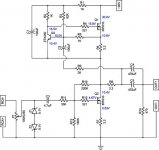
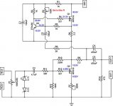
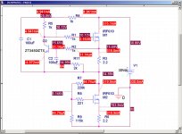
Today, unable to wait for my transformer to arrive to complete the project, I hooked it up to a variable DC power supply, and slowly fed it voltage until it was running off 30V. The good news, no pops, sparks or smoke! The bad news, the bias is only ~250mA and the drain of Q2 is at 10.4V referenced to ground instead of ~15. I am posting the schematic with the measured voltage at various points labelled in blue.
My thought at this point is that I need to replace R3 and R13 with pots (200K?) to allow me to adjust the bias and the voltage of Q2's drain. I'd appreciate and feedback of help that can be offered.
Attachments
Shooting from the hip having never built a zen or aleph, but the Vbe of Q3 looks low - if it was the standard .66 volts (as shown in Zen V4) you'd end up with more current - perhaps 300 mA. What current were you expecting? Odd that both channels ended up this way, but maybe new ZTX450s would help. Lowering the current source resistor will increase the bias.
A pot for R13 probably would be a good idea - Q2 seems turned on too much. Z V4 has the ratios of your R10 and R13 at least 2:1. You could try 75K-100K for R13, too, which should not turn on Q2 so much.
Odd that R4 shows DC current - you'd expect no DC current with a good mosfet.
Hope that this helps a little.
I like vary much Zen design, and have buid some samples of ZenV4 and hybrid - ZenV3 with tube (6N23P) SRPP input stage - all work very nice!
But for the headamp - I'm not clearly understand why You use so complicate schematics?
Idle current 250-300mA - the low impedance (40 Ohm) headphones works very well, and with the rail of 30v - it is quite enough to drive any 600 Ohm headphones, without controlable current source!
So, I use more simple schematic - LM317 as a current source at the top, and IRF510 at the bottom, powered from "electronic capacitor" - i.e. mosfet with capacitor from the gate to ground. Of course, it possible to put also a zenner in parallel, to obtain not only filtered but alse stabilozed voltage, but I havn't do this, think it is not nessesary.
http://altor.sytes.net/headamp.jpg
But for the headamp - I'm not clearly understand why You use so complicate schematics?
Idle current 250-300mA - the low impedance (40 Ohm) headphones works very well, and with the rail of 30v - it is quite enough to drive any 600 Ohm headphones, without controlable current source!
So, I use more simple schematic - LM317 as a current source at the top, and IRF510 at the bottom, powered from "electronic capacitor" - i.e. mosfet with capacitor from the gate to ground. Of course, it possible to put also a zenner in parallel, to obtain not only filtered but alse stabilozed voltage, but I havn't do this, think it is not nessesary.
An externally hosted image should be here but it was not working when we last tested it.
http://altor.sytes.net/headamp.jpg
Did my homework last night and figured out at least part of the problem. I was on the right track, and Bob confirmed it for me. R13 is too large, and a correct value should be around 130K, so I will replace R13 with a 100K resistor plus a 100K trimpot in series later today and see what effect that has on my current source problem.
As to why I am using the Aleph current source? I built the original Zen a couple of years ago, and I want to build another power amp, maybe a Zen4 or an Aleph 5 or an Aleph-X - haven't decided yet, and since I need a headphone amp I thought this would be a good exercise in playing with a more complicated topology on a smaller scale before I sale up to a larger project.
Thanks everyone for the suggestions and insight, and I will update how the toubleshooting goes as I make some progress.
Metalman
Progress with Trimpots
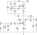
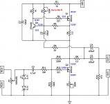
Over my lunch break I replaced R13 on both channels with 500K trimpots, powered them up and Voila! After a little adjusting the drain of Q2 is sitting happily at 15.1V. One problem down, one to go!
I am posting my revised schematic again with the new measured voltages reference to ground listed again in blue. Of particular concern to me is tha fact that the base of Q3 is at a lower voltage than the emitter. My suspicion is that the value of R3 is too high creating too much of a voltage drop at Q3's gate. My plan is to remove R3 altogether, check the voltages again, and depending on what happens, I may replace it with a 100K trimpot.
Once again, any comments or suggestions will be greatly appreciated. Fun stuff this DIY, and so far haven't hit a brick wall!
Attachments
AAARGHHHHH!
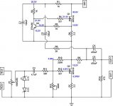
OK! Now I'm really confused! I replaced R3 with a 100K trimpot on both channels, connected it to a 30VDC supply, set R3 to max resistance (100K) and took some measurements. The schematic below shows what I found, which is not what I expected.
OK! Now I'm really confused! I replaced R3 with a 100K trimpot on both channels, connected it to a 30VDC supply, set R3 to max resistance (100K) and took some measurements. The schematic below shows what I found, which is not what I expected.
Attachments
So next, I set R3 to the minimum resistance value, waited a bit for the circuit to stabilize, took more measurements, and found these results. These combined results have me completely confused, and I still don't understand why the base voltage always stays lower then the emitter voltage. Is it possible that I have Q3 in backwards (i.e. emitter attached to R2)? I was pretty careful about that but at this point I'm willing to believe I could be wrong.
By the way, both channels are doing pretty much exactly the same thing.
Greater minds of the forum, please help!
By the way, both channels are doing pretty much exactly the same thing.
Greater minds of the forum, please help!
Attachments
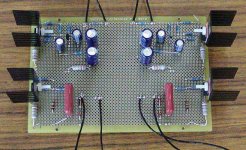
Hi metalman,you main board look very neat,it's let I remember my first one zen headamp
Have you tried to adjust her voice? About DC point, I advise you match the R7 and R6.
In addition, feedback loop of the active side of the circuit (Q2) will exert a tremendous influence to the sound. Some my diy friends propose that C2 should use a good one.
another playing method,put a little film capacity between b and c electrode of Q3.
regards,digi01
Still Confused, but it Works!
Well, I tried setting R3 to various different levels, and there was a smooth inverse correlation between the value of R3's resistance and the resulting bias current. Lowering the resistance increased the bias and vice versa. Is this the way it is supposed to work. I also double checked, and I definitely have Q3 installed correctly.
Frustrated, I went back and reviewed (for the thousandth time) Nelson's Zen articles, and decided that since Nelson doesn't include R3, I'd disconnect mine. Without R3 the bias is ~260mA with a 0.56V drop across R6. However, the base of Q3 is still 0.87V lower than the emitter, which doesn't look right to me, and certainly contradicts what is in Nelson's articles. Currently, these are the voltage measurements referenced to ground.
Attachments
So after all that I scratched my head and decided what the hell, it's sort of working, so I wired up the input and output connectors, connected it to the audio out of my laptop, plugged in my headphones and fired it up from a variable DC power supply. First thing I noticed is that the DC supply I have been using is pretty noisy. Without any music you can hear a nice 60Hz hum and a good dollop of hiss and noise. Oh well, I figured that would dissappear when I get the amps own PS built once the transformer arrives.
Dropped a CD in, hit play and was quite alarmed, as it sounded muddy, flat and lifeless. Had a moment of panic for a bit thinking that this issue surrounding Q3 was really making for a crappy sounding amp. Then common sense set in and I realized that this amp had never had a signal put through it before, and maybe I should give it some time to break in. So I wired the input for the left channel out of phase with the right, hooked it back up, crancked the volume, put the headphones in a drawer and left it play for 2.5 hours.
Break in definitely makes a difference. Much more dynamic now, certainly not muddy anymore, and sounding pretty good now. Still doesn't seem to sound quite right though (Yes, I did correct the polarity on the left channel!).
This problem with Q3 is still driving me nuts though, especially considering that the exact same behaviour is happening in both channels. I'd kill for some seasoned feedback on what might be going on about now. I have exhausted my bag of tricks from what I learned back in my second year electrical engineering course, i.e. I can tell how it is working but I can't quite grasp how to make that ZTX450 behave the way design says it should.
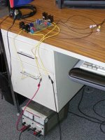
Anyway, here is a pic of the amp jury rigged to run off my laptop.
Dropped a CD in, hit play and was quite alarmed, as it sounded muddy, flat and lifeless. Had a moment of panic for a bit thinking that this issue surrounding Q3 was really making for a crappy sounding amp. Then common sense set in and I realized that this amp had never had a signal put through it before, and maybe I should give it some time to break in. So I wired the input for the left channel out of phase with the right, hooked it back up, crancked the volume, put the headphones in a drawer and left it play for 2.5 hours.
Break in definitely makes a difference. Much more dynamic now, certainly not muddy anymore, and sounding pretty good now. Still doesn't seem to sound quite right though (Yes, I did correct the polarity on the left channel!
).This problem with Q3 is still driving me nuts though, especially considering that the exact same behaviour is happening in both channels. I'd kill for some seasoned feedback on what might be going on about now. I have exhausted my bag of tricks from what I learned back in my second year electrical engineering course, i.e. I can tell how it is working but I can't quite grasp how to make that ZTX450 behave the way design says it should.
Anyway, here is a pic of the amp jury rigged to run off my laptop.
Attachments
Re: Still Confused, but it Works!
I like debugging stuff.... You've got a pretty interesting problem here.
I'm going to just point out some (hopefully) obvious stuff here and hope it points you in the right direction for finding a solution.
Firstly, assuming your measurements are accurate and confirming that because both channels operate the same, you have the same voltage drop on both 2.2R's so that means the current is definately flowing through Q2. Good news because if Q2 was cut-off then you'd be sol to begin with.
So, since that has been established, we'll start by assuming that the Caps works properly (if you measured the bottom of C2 you could confirm this) and aren't shorted. C1 is the only POSSIBLE suspect device but very unlikely.
Therefore, the current flowing into R6 can only come from 2 places, the MOSFET source terminal OR the BJT base. We can't rule anything out.
By observing your potentials, there is several worrisom issues to consider:
1) The current flowing through R1 is not the same as the current flowing through R1 by 1ma. I hope this is just a slight measurement error or else C1 is trickling current through.
2) There is also apparently a slight current flowing OUT of the gate of Q1. This is a real issue for a MOSFET.
3) There is current flowing into Q3s base. ~1ma which is a very significant base current.
4) Both junctions of Q3 are reversed biased which should cause no current to flow.
Conclusion:
There seems to be a necessary voltage Vgs for Q1 to allow current to flow through it. In fact, Q1 is the only possible source for the current to flow because all the other current flows the wrong way.
Unfortunately, you've got some contradictions: while current is flowing into Q3, there is no current flowing out of it according to the measurements. This is an impossibility especially considering that Q3 is reversed biased.
Technically, this circuit shouldn't be working as you described it...
metalman said:Well, I tried setting R3 to various different levels, and there was a smooth inverse correlation between the value of R3's resistance and the resulting bias current. Lowering the resistance increased the bias and vice versa. Is this the way it is supposed to work. I also double checked, and I definitely have Q3 installed correctly.
Frustrated, I went back and reviewed (for the thousandth time) Nelson's Zen articles, and decided that since Nelson doesn't include R3, I'd disconnect mine. Without R3 the bias is ~260mA with a 0.56V drop across R6. However, the base of Q3 is still 0.87V lower than the emitter, which doesn't look right to me, and certainly contradicts what is in Nelson's articles. Currently, these are the voltage measurements referenced to ground.
I like debugging stuff.... You've got a pretty interesting problem here.
I'm going to just point out some (hopefully) obvious stuff here and hope it points you in the right direction for finding a solution.
Firstly, assuming your measurements are accurate and confirming that because both channels operate the same, you have the same voltage drop on both 2.2R's so that means the current is definately flowing through Q2. Good news because if Q2 was cut-off then you'd be sol to begin with.
So, since that has been established, we'll start by assuming that the Caps works properly (if you measured the bottom of C2 you could confirm this) and aren't shorted. C1 is the only POSSIBLE suspect device but very unlikely.
Therefore, the current flowing into R6 can only come from 2 places, the MOSFET source terminal OR the BJT base. We can't rule anything out.
By observing your potentials, there is several worrisom issues to consider:
1) The current flowing through R1 is not the same as the current flowing through R1 by 1ma. I hope this is just a slight measurement error or else C1 is trickling current through.
2) There is also apparently a slight current flowing OUT of the gate of Q1. This is a real issue for a MOSFET.
3) There is current flowing into Q3s base. ~1ma which is a very significant base current.
4) Both junctions of Q3 are reversed biased which should cause no current to flow.
Conclusion:
There seems to be a necessary voltage Vgs for Q1 to allow current to flow through it. In fact, Q1 is the only possible source for the current to flow because all the other current flows the wrong way.
Unfortunately, you've got some contradictions: while current is flowing into Q3, there is no current flowing out of it according to the measurements. This is an impossibility especially considering that Q3 is reversed biased.
Technically, this circuit shouldn't be working as you described it...
Azira, thanks very, very much for the feedback!
As you suggested, let's start with the basics!
"assuming your measurements are accurate"
So far I have been making all measurements with a Fluke Model 79 Mk III digital multimeter, connecting the COM probe to ground, and the measurement probe to the points indicated on the schematic by the voltage reading. I think this is a correct way, but then again, I'm a metallurgist/corrosion engineer, not an EE, and I think of potential measurements in electrochemical terms. Please correct me if I am wrong.
"we'll start by assuming that the Caps works properly (if you measured the bottom of C2 you could confirm this)"
The measurements have shifted aroung a bit after the burn in period, but I think this should partly answer your question. The junction between C4 and R9 measures 14.91V and the junction between R9 and C2 measures 14.14V, which says current is flowing into the negative terminal of C2, but then I measure the junction between C2 and Q3 at 14.49V which doesn't make sense. Then I place the probes at either end of R9 and I get a reading of 0.00V.
I just noticed something different again as I was getting you those measurements. A quick clarification on terminology first. When I say I am measuring A referenced to B, I mean that I have the positive probe connected to A and COM probe connected to B for the measurement. Following that terminology, I get the base of Q3 reading +0.47V referenced to the emitter. Next the collector reads +4.54V reference to the emitter, and the collector reads +3.58V referenced to the base. The collector of Q3 reads 20.13V, the base 14.49, and the emitter 14.82, all reference to ground. What does this say about my measurements??? I am beginning to think that perhaps I should remeasure using a different (better?) instrument.
A last note, if I measure the emitter reference to the base I get -0.61V, not the -0.47 I would expectfrom the above measurement.
OK, anyone want to give me a tutorial on how to measure voltage???
Well, I didn't nearly mean to imply that you didn't know how to use a DMM. You might have a chosen various reference points that were inconsistent however.
There should be no DC voltage across R9. So 0.00 is good. I personally use a cheap DMM that I got at a good price from a local hobby store. It's got a thermal couple so I'm happy.
So, those numbers you quotes for Q3 are all in the right direction. So that's reassuring.
Here's a sim I just did about what you should expect.
I have a suggestion. Try measuring Vbe of Q3 while adjusting R13. Turn it up a little and see if you can get that .47 to be more like .65 or .7. I noticed in my sims while trying to find the right value of R13 that if it was too low, Q3 got cut off although bias current still was able to flow. This was because the Vgs potential across Q1 was more than the threshold. If this works, then you might have to bias Q2 a little higher than 1/2 Vcc and live with it. But at 30volts and headphones I'd say you don't need that much headroom.
In principle, you should be able to run a lower rail voltage with exactly the same circuit and have no problems once you nail the values right.
There should be no DC voltage across R9. So 0.00 is good. I personally use a cheap DMM that I got at a good price from a local hobby store. It's got a thermal couple so I'm happy.
So, those numbers you quotes for Q3 are all in the right direction. So that's reassuring.
Here's a sim I just did about what you should expect.
I have a suggestion. Try measuring Vbe of Q3 while adjusting R13. Turn it up a little and see if you can get that .47 to be more like .65 or .7. I noticed in my sims while trying to find the right value of R13 that if it was too low, Q3 got cut off although bias current still was able to flow. This was because the Vgs potential across Q1 was more than the threshold. If this works, then you might have to bias Q2
a little higher than 1/2 Vcc and live with it. But at 30volts and headphones I'd say you don't need that much headroom. In principle, you should be able to run a lower rail voltage with exactly the same circuit and have no problems once you nail the values right.
Attachments
Thanks Azira,
I know you didn't mean to suggest any lack of knowledge on my part, but this whole scenario has me questioning the problem from every perspective including user error.
Thanks for your new suggestion. What you are suggesting follows logically from my perspective. Unfortunately I left the amp at work where I have access to equipment, so I'll give it a try over lunch tomorrow. Thanks again for your feedback and suggestions. They definitely are helping me to move in the right direction.
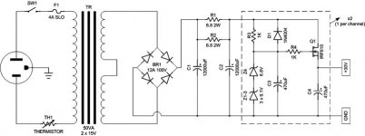
The 30V rails are because I could get a transformer with 24 or 30 V output, and I really wanted to regulate the output, so I needed about an 8V overhead. with the 24 V transformer output it was going to drop the PS voltage a little too low, so I went with the 30V output transformer, which after rectification, a CRC filter and regulation stage leaves me with 30. I could lower that, but hey, isn't more power always better
BTW, With a few more hours of burn-in under its belt the amp is actually getting to sound better than pretty good.
I know you didn't mean to suggest any lack of knowledge on my part, but this whole scenario has me questioning the problem from every perspective including user error.
Thanks for your new suggestion. What you are suggesting follows logically from my perspective. Unfortunately I left the amp at work where I have access to equipment, so I'll give it a try over lunch tomorrow. Thanks again for your feedback and suggestions. They definitely are helping me to move in the right direction.
The 30V rails are because I could get a transformer with 24 or 30 V output, and I really wanted to regulate the output, so I needed about an 8V overhead. with the 24 V transformer output it was going to drop the PS voltage a little too low, so I went with the 30V output transformer, which after rectification, a CRC filter and regulation stage leaves me with 30. I could lower that, but hey, isn't more power always better
BTW, With a few more hours of burn-in under its belt the amp is actually getting to sound better than pretty good.
I use a 24V powersupply on my Zen and it's damn loud... loud enough for my garage while I'm working anyway...
But actually the main difference between your zen and mine (well I used the original CCS) is the bias current. If you biased it up, you could use it for loudspeakers, although you'd need a bigger heatsink.
good luck, let me know how it goes.
--
Danny
But actually the main difference between your zen and mine (well I used the original CCS) is the bias current. If you biased it up, you could use it for loudspeakers, although you'd need a bigger heatsink.
good luck, let me know how it goes.
--
Danny
- Status
- This old topic is closed. If you want to reopen this topic, contact a moderator using the "Report Post" button.
- Home
- Amplifiers
- Headphone Systems
- Zen Headphone Amp Lives (Sort of!)