OK Danny,
I tried shifting around the midpoint voltage between Q1 and Q2, and as with how things have been going so far, what happened is not what we hoped. Adjusting R13 so that Q2 Vds was 20V resulted in almost no change at all in Q3's Vbe. Just to gather more info, I readjusted so that Q2's Vds was 10V and Q3's Vbe increased slightly to 0.50V, and the Bias current increased to a little over 300 mA. Interestingly, I had a listen to the amp at both settings, and the sound was substantially better at the lower Q2 Vds.
Next, just to try to compare efects of rail voltage and see if a lower rail voltage made any difference, I reset the Vds evenly for Q1 and Q2 and listened to the circuit at 15V, 23V, 30V and 38V. There was a noticeable increase in the gain of the circuit at 23V rails, but also a large increase in the distortion of the circuit as well as a drop in PS noise rejection. At 15V, 30 and 38V the gain was quite a bit lower, but the sound was MUCH cleaner and the PS noise rejection was better. Overall, the 15V rails produced the best sound!
Overall, I think this is a pretty clear idication that I might have been a little heavy handed when I soldered in my BJT's and overcooked them a bit, as the more I analyze the behaviour, everything is behaving according to the datasheet information except the BJT's. According to the datasheet, below 0.6Vbe the Ice should be limited to around 1mA putting Q1's Vgs well above 5V causing it to conduct wildly. I have seen Q3's Ice at over 10mA at a Vbe of 0.50V, which should never happen according to the datasheet. Does this make sense?
So I think I'll swap them out (luckily I ordered extras when I started this project) and see if that makes any difference. I still haven't received my transformer from Plitron, and the wife is making me a list of household chores, so it may be a day or two before I get around to it. I'll keep posting my progress as I move along.
Terry (aka Metalman)
One more thing to double check when you put it in there is if you have the terminals the right way. BJTs will work if you put them in backwards... sort of. They can act like really bad BJTs. The only other thing to make sure is that you have the pin assignments right, some transistors are made BCE instead of CBE. The datasheet I downloaded says that they are CBEs though.
good luck
good luck
A different direction
Took a break from troubleshooting, and my transformer won't be arriving for at least another week, so I decided to build my CRC filter and voltage regulator circuits. This way I can reduce the noise on my variable DC power supply (or find out that there is no noise on my DC supply!) when I do further testing on the map after I make the next set of changes. I'll post a photo or two of the voltage regulator board tomorrow (forgot to bring the digital camera home fom work!). I think it looks pretty neat and tidy, but then again, I'm rather partail to my own work.
Took a break from troubleshooting, and my transformer won't be arriving for at least another week, so I decided to build my CRC filter and voltage regulator circuits. This way I can reduce the noise on my variable DC power supply (or find out that there is no noise on my DC supply!) when I do further testing on the map after I make the next set of changes. I'll post a photo or two of the voltage regulator board tomorrow (forgot to bring the digital camera home fom work!). I think it looks pretty neat and tidy, but then again, I'm rather partail to my own work.
Success!!!
Finally got around to switching out the BJT's, and now I am getting measurements from the current source that make sense. I'm still not getting the 300mA bias I designed for, but I am getting 261mA Bias with the Vbe at 0.565V, a current of a few microamps at the BJT base. It isn't exactly what I was shooting for, but seeing as all the measurements are in the ballpark of what they are supposed to be and behaving in the expected fashion, I figure the circuit is working correctly.
Seem to have misplaced my digital camera, so may be a few days before I can post any photos of my voltage regulator board. Besides, my transformer from Plitron won't be arriving until the beginning of next week anyway. Time to work on the container.
One question: I didn't want to go to tyhe full expense of separate power supplies for each channel, but I wanted to isolate the channels as much as possible. So I went with splitting the supply after the CRC filter but before the voltage regulation stage. Is separate voltage regulation on each channel likely to provide a significant benefit?
Congrats!!! That's good news. 0.57 Volts is -BARELY- enough to turn on a BJT... actually it seems almost too low, make sure you hvae current flowing through the 1k collector resistor to be positive (should be a voltage drop across it). I'm still a little wary that it might not be working right.
With respect to the powersupply, that is way beyond me....
My zen has 8000uF of filtering, the PS I took apart to use for this quotes up to 2.1Vpp of ripple. Personally I've never heard the difference... Then again, I'm using a boombox headphone output to drive it and there is all kinds of noise (static, CD spin up...) besides music coming out of that thing. Not exactly what you'd call an ideal or hi-fi set up. It works for my garage though to give me music while I'm working on bigger and better things.
Oh yeah, and I'm using an athlon heatsink / channel to cool it which I believe swamps out ripple hum
I think I'm going to get banned or shunned from diyaudio.com for telling everyone what I used for my Zen
Danny,
I'm agree with you about the Vbe reading, but the voltage drop across the collector resistor indicates roughly 4.5mA running through it. According to the ZTX450 data sheet this should correspond to a Vbe of ~0.64V. But I triple checked the orientation of the BJT Leads (even harassed the wife into scrutinizing the data sheet and squinting at the transistor through a magnifying glass for a second opinion ), and took extreme painstaking care to solder them in with an absolute minimum of thermal effect, and last but not least I'm out of spare BJT's
 The only opther indication I have is that if I change the R13 pot to get a larger voltage drop across the CCS mosfet, the bias current goes up, which my homemade mathematic circuit model predicts should happen.
This project for me is also a trial run at bigger and better things as well, to make sure I can put my money where my mouth is before I spend the money. Definitely discovered that I'm not ready for an Aleph-X, but a Zen V4 or an Aleph 5 look within reasonable reach, and I've committed to the Canadian Heatsink Group Purchase towards that end. Don't worry about being strung up by the forum for your Zen amp usage. Once they figure out I'm building the chassis for my headphone amp out of 1/4" MDF they'll be too busy hunting me down. (No one will ever confuse my work with Peter Daniel's )
)
I'm agree with you about the Vbe reading, but the voltage drop across the collector resistor indicates roughly 4.5mA running through it. According to the ZTX450 data sheet this should correspond to a Vbe of ~0.64V. But I triple checked the orientation of the BJT Leads (even harassed the wife into scrutinizing the data sheet and squinting at the transistor through a magnifying glass for a second opinion
), and took extreme painstaking care to solder them in with an absolute minimum of thermal effect, and last but not least I'm out of spare BJT's The only opther indication I have is that if I change the R13 pot to get a larger voltage drop across the CCS mosfet, the bias current goes up, which my homemade mathematic circuit model predicts should happen.This project for me is also a trial run at bigger and better things as well, to make sure I can put my money where my mouth is before I spend the money. Definitely discovered that I'm not ready for an Aleph-X, but a Zen V4 or an Aleph 5 look within reasonable reach, and I've committed to the Canadian Heatsink Group Purchase towards that end. Don't worry about being strung up by the forum for your Zen amp usage. Once they figure out I'm building the chassis for my headphone amp out of 1/4" MDF they'll be too busy hunting me down. (No one will ever confuse my work with Peter Daniel's
)
Hello,
I have made a Marcello Pellerano Zen headphone amp. Simply marvelous (like all N. Pass amplifiers )
You can see it here http://www.ptsoundlab.com/secelectro/ampcasques/pelleranoca/pelleranoca.htm
Cordially.
Pascal.
I have made a Marcello Pellerano Zen headphone amp. Simply marvelous (like all N. Pass amplifiers
)You can see it here http://www.ptsoundlab.com/secelectro/ampcasques/pelleranoca/pelleranoca.htm
Cordially.
Pascal.
It Lives!
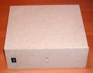
Well, it is finally, mostly completed. Actually received my transformer two weeks ago, but have been too busy to follow up on it (Damn career gets in the way ). Completed the power supply, finished building the basic chassis, mounted all the parts, wired it together, powered it up and viola ... no smoke!
Funny thing is that all the Aleph CS issues I was concerning myself over have dissappeared now that I have it powered off its P/S. Suddenly my steady state bias is pretty much spot on 300mA. Can't say for sure what that is all about, but I'm filing that one under "All's well that ends well".
The Sound: Well, it is pretty damn good. My Grado Labs SR225's now have a very solid bass region with great extension down low, and I now have enough power for ungodly volume levels. Akira was right, 30V rails with 0.3A bias per channel is definitely overkill. There is also a liquidity present that was never there before.
One last problem remains. I have a bit of hum present, which I suspect is being radiated from the power supply, or maybe from a groundloop problem. It isn't particularly loud, just enough to be audible over the music, it is louder in the left channel than the right and its volume increases when I turn up the volume control. My concern is that the AC wiring running to the front panel power switch runs parallel to the mosfets of the left channel. I'm going to be inserting some shielding bewteen the P/S section and the amplifier section to find out if that is the problem. On the grounding side all I have so far is a 10ohm power resistor bewteen circuit ground and IEC ground terminal. Guess I should beef that up too. But before that I really need to get my volume control shaft and knob made.
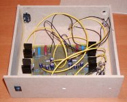
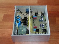
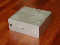
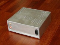
Here are some shots of the current progress.
Well, it is finally, mostly completed. Actually received my transformer two weeks ago, but have been too busy to follow up on it (Damn career gets in the way
). Completed the power supply, finished building the basic chassis, mounted all the parts, wired it together, powered it up and viola ... no smoke!Funny thing is that all the Aleph CS issues I was concerning myself over have dissappeared now that I have it powered off its P/S. Suddenly my steady state bias is pretty much spot on 300mA. Can't say for sure what that is all about, but I'm filing that one under "All's well that ends well".
The Sound: Well, it is pretty damn good. My Grado Labs SR225's now have a very solid bass region with great extension down low, and I now have enough power for ungodly volume levels. Akira was right, 30V rails with 0.3A bias per channel is definitely overkill. There is also a liquidity present that was never there before.
One last problem remains. I have a bit of hum present, which I suspect is being radiated from the power supply, or maybe from a groundloop problem. It isn't particularly loud, just enough to be audible over the music, it is louder in the left channel than the right and its volume increases when I turn up the volume control. My concern is that the AC wiring running to the front panel power switch runs parallel to the mosfets of the left channel. I'm going to be inserting some shielding bewteen the P/S section and the amplifier section to find out if that is the problem. On the grounding side all I have so far is a 10ohm power resistor bewteen circuit ground and IEC ground terminal. Guess I should beef that up too. But before that I really need to get my volume control shaft and knob made.
Here are some shots of the current progress.
Attachments
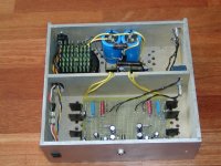
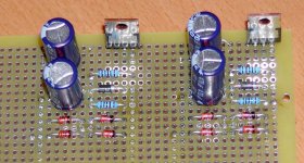
The power supply. Plitron 50VA transformer with dual 15V secondaries connected in series. Pi filter is 12,000uF - 4ohm - 12,000uF connected to separate voltage regulator circuits for each channel. I only have 470uF of filter capacitance per channel after the regulators, so I will probably look at increasing that as a future upgrade.
Attachments
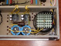
Another view from the side. I am using an Alps Blue Velvet 100Kohm dual potentiamoter as a volume control. My wiring layout for the conntection from the regulators to the amplifier board is less than optimal, which could also be causing the hum problem. Unfortunate case of building the chassis in a rush and realizing I hadn't drilled all the wiring holes in the divider before I glued it in. Oh well, it's only MDF.
Attachments
- Status
- This old topic is closed. If you want to reopen this topic, contact a moderator using the "Report Post" button.
- Home
- Amplifiers
- Headphone Systems
- Zen Headphone Amp Lives (Sort of!)