The O2 is widely hailed as state of the art headphone amp, including by many here. I was curious to see what the hub-hub was about, so I decided to pick one up and run it through its paces on my Audio Precision APx525 audio analyzer.
You can find my full review and measurements here: O2 Headphone Amp Review & Measurements.
A couple of the more telling plots are below.
As the O2 is battery powered, I also measured its performance as the batteries die. The graph below shows the O2 delivering 200 mW into 32 Ω for about 2.5 hours at which point the batteries run out of charge and the amp starts misbehaving.
Once the batteries die, this is what the output voltage of the amp looks like vs time. This behaviour is a known issue, and the instructions from JDS Labs warn that operating the amplifier with the output chattering like that may damage your headphones.
The erratic behaviour of the O2 as the batteries die is a design flaw. NwAvGuy does indicate on his blog that he is aware of the flaw but basically brushes it off as "my unit works fine; others may not". That's inexcusable. The issue is that there isn't enough hysteresis in the low battery detection circuit. The solution is to use a battery management IC or to add a latch such that once the low battery detection circuit triggers, the amp turns off and remains off until the next cycling of the power switch. Using a battery management IC with a built-in charging circuit could also have dramatically reduced the battery recharge time of the O2.
Once the batteries are dead, it takes about 14-16 hours to recharge them fully.
If you decide to buy or build an O2, I strongly suggest that you operate it powered with the included AC adapter
I can of course easily be caused of being biased, in particular as I offer a competing product for sale. However, my assembled HP-1 is ten times the cost of the assembled O2 from JDS Labs, so I wouldn't worry too much about competition here.
My goal is to provide enough data that people can get an idea of what they're getting. That's all.
Tom
You can find my full review and measurements here: O2 Headphone Amp Review & Measurements.
A couple of the more telling plots are below.
An externally hosted image should be here but it was not working when we last tested it.
An externally hosted image should be here but it was not working when we last tested it.
An externally hosted image should be here but it was not working when we last tested it.
An externally hosted image should be here but it was not working when we last tested it.
As the O2 is battery powered, I also measured its performance as the batteries die. The graph below shows the O2 delivering 200 mW into 32 Ω for about 2.5 hours at which point the batteries run out of charge and the amp starts misbehaving.
An externally hosted image should be here but it was not working when we last tested it.
Once the batteries die, this is what the output voltage of the amp looks like vs time. This behaviour is a known issue, and the instructions from JDS Labs warn that operating the amplifier with the output chattering like that may damage your headphones.
An externally hosted image should be here but it was not working when we last tested it.
The erratic behaviour of the O2 as the batteries die is a design flaw. NwAvGuy does indicate on his blog that he is aware of the flaw but basically brushes it off as "my unit works fine; others may not". That's inexcusable. The issue is that there isn't enough hysteresis in the low battery detection circuit. The solution is to use a battery management IC or to add a latch such that once the low battery detection circuit triggers, the amp turns off and remains off until the next cycling of the power switch. Using a battery management IC with a built-in charging circuit could also have dramatically reduced the battery recharge time of the O2.
Once the batteries are dead, it takes about 14-16 hours to recharge them fully.
An externally hosted image should be here but it was not working when we last tested it.
If you decide to buy or build an O2, I strongly suggest that you operate it powered with the included AC adapter
I can of course easily be caused of being biased, in particular as I offer a competing product for sale. However, my assembled HP-1 is ten times the cost of the assembled O2 from JDS Labs, so I wouldn't worry too much about competition here.
My goal is to provide enough data that people can get an idea of what they're getting. That's all.
Tom
Interesting measurements, thanks.
Like your measures show, a low battery condition is likely to generate a very much audible effect (in terms of THD), which should be a nice warning sign for the user to shut off the unit.
While not being fan at all of the O2 design (for me the fixed, full steam, gain of the first stage is worse than battery shut-off, FWIW), there are trade offs you need to accept, when you have to keep cost under control, and PCB space (especially when choosing a through-hole design to ease DIY).
I am betting quite a few of the sub $200 battery powered amps would suffer from similar behavior.
tomchr - great work! Finally, some AP measurements on the O2 done by someone who isn't selling the O2.
I haven't tried comparing them with NwAvGuy's published dScope results yet. I'm curious if there are any major discrepencies:
NwAvGuy: O2 Headphone Amp
and/or if he cherry picked any test conditions.")
We've had some speculation going that the gain-stage 1.5K feedback resistor in parallel with the 10K pot may exceed the datasheet 2K load they used for several of the specs, hence possibly a bit of increased THD from that:
http://www.diyaudio.com/forums/head...rc-diode-cap-heatsink-mods-3.html#post4897870
http://www.diyaudio.com/forums/head...rc-diode-cap-heatsink-mods-3.html#post4898441
His power management circuit definitely needs a latch. I had that discussion with him once via PM way back when and we agreed it was a 3 state problem that would be harder to solve with analog. His PM circuit starts up off, to attempt to eliminate turn-on thumps, then turns on, then turns off when the batteries get low. That initial "off" period tends to trigger latch circuits so the whole thing just never starts up. I thought I had it solved a couple of years ago:
http://www.diyaudio.com/forums/head...rc-diode-cap-heatsink-mods-3.html#post4293487
two mosfets in series with the first one as a "lock out" fed by an RC delay, with the second as the latch. Worked great, at least until I found a glitch. If the O2 is running on batteries and the AC is plugged in, it would trigger the latch.
I haven't tried comparing them with NwAvGuy's published dScope results yet. I'm curious if there are any major discrepencies:
NwAvGuy: O2 Headphone Amp
and/or if he cherry picked any test conditions.
We've had some speculation going that the gain-stage 1.5K feedback resistor in parallel with the 10K pot may exceed the datasheet 2K load they used for several of the specs, hence possibly a bit of increased THD from that:
http://www.diyaudio.com/forums/head...rc-diode-cap-heatsink-mods-3.html#post4897870
http://www.diyaudio.com/forums/head...rc-diode-cap-heatsink-mods-3.html#post4898441
His power management circuit definitely needs a latch. I had that discussion with him once via PM way back when and we agreed it was a 3 state problem that would be harder to solve with analog. His PM circuit starts up off, to attempt to eliminate turn-on thumps, then turns on, then turns off when the batteries get low. That initial "off" period tends to trigger latch circuits so the whole thing just never starts up. I thought I had it solved a couple of years ago:
http://www.diyaudio.com/forums/head...rc-diode-cap-heatsink-mods-3.html#post4293487
two mosfets in series with the first one as a "lock out" fed by an RC delay, with the second as the latch. Worked great, at least until I found a glitch.
If the O2 is running on batteries and the AC is plugged in, it would trigger the latch.Interesting measurements, thanks.
Like your measures show, a low battery condition is likely to generate a very much audible effect (in terms of THD), which should be a nice warning sign for the user to shut off the unit.
Except the sharp rise in THD when the batteries die occurs because of the erratic pulsing behaviour. If you happen to be listening at the time, you'll definitely notice. If you, like I, like to listen to music at night and forget to turn the amp off before going to bed, you may wake up to a nasty surprise.
While not being fan at all of the O2 design (for me the fixed, full steam, gain of the first stage is worse than battery shut-off, FWIW), there are trade offs you need to accept, when you have to keep cost under control, and PCB space (especially when choosing a through-hole design to ease DIY).
The gain of the first stage is switchable. The output is a buffer. That makes a lot of sense, actually. For the best noise performance in a headphone amp or preamp, you want to amplify then attenuate. Otherwise, you'll end up amplifying the noise of the volume pot.
I do agree that it would be nice with a lower gain option on the O2.
I am betting quite a few of the sub $200 battery powered amps would suffer from similar behavior.
For DIY amps where battery management tends to be a bit of an afterthought (as it clearly was in the O2) you're probably right. Exactly how the amp dies would depend on the batteries and the opamps chosen. A design by a more experienced DIYer or professional engineer would include power management. This would include graceful shutdown of the amp when the battery dies, a fast charging circuit, and a battery charged indicator. There are tons of PMICs out there that do just that.
Tom
The gain can be lowered very easily. This quick fix was mentioned in an O2 thread here on DIYaudio.com a number of years ago.
The low gain position stays the same, but just clip the resistor to ground for the high gain setting and it now becomes unity and lower than the low gain position.
Dave.
The low gain position stays the same, but just clip the resistor to ground for the high gain setting and it now becomes unity and lower than the low gain position.
Dave.
NwAvGuy does his THD test relative to 400mV output which I guess he says most portable amps can't go above 500mV. If you repeat the test at 400mV maybe a more apple to apples comparison can be made.
From: NwAvGuy: O2 Headphone Amp
I have measured Agdr's Super CMOY 1688 at 700mV and it does quite admirably with a nice harmonic profile of mostly H2 and a little H3 and not too much of other stuff, although H6 and H8 start to rise up. Agdr's design has no buffer - just a straight opamp. The power management on the Super CMOY 1688 is exceptional though with rail-cut MOSFETs controlled by a comparator. Turn on thump is suppressed with dual MOSFET latch, which also serves to shutoff quickly to prevent turn-off thump.
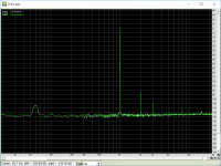
Here is the measured FFT at 1kHz and driving 270R load at 700mV (as measured with Focusrite Solo 2G at 96kHz and 24bit):

It's puzzling why there is a small bump at 60Hz as the amp is battery powered as well as the laptop and audio interface. Same interface on my Pocket Class A has no 60Hz bump.
By contrast, your measurement of the O2 FFT almost looks like there is some mild oscillation going on, albeit at very low levels as the FFT is kind of lighting up like a Xmas tree forest with all those higher order spikes. I wonder if a compensation cap(s) may be off. I had a similar experience on the Super CMOY when I ran it temporarily with 10pF comp caps instead of 47pF compensation caps. Or is is simply the AP gear is able to reach down into the -150dB noise floor so the "trees" look taller?

From: NwAvGuy: O2 Headphone Amp
NEW NOISE REFERENCE: I’ve used 400 mV as my reference level instead of the more typical industry standards of dBV (1 volt RMS) or dBU (775 mV) because a lot of portable gear can’t output anything over 500 mV. But, it’s easy enough to adjust noise figures to different references. So, where applicable, I’m going to to use the industry standard dBV for noise measurements from here forward. To convert dBV to my previous 400 mV dBr values, subtract 8 dB. To convert from 400 mV to dBV just add 8 dB. The dScope reads in dBV directly. It also makes it easier to compare my data to the data published by others.
I have measured Agdr's Super CMOY 1688 at 700mV and it does quite admirably with a nice harmonic profile of mostly H2 and a little H3 and not too much of other stuff, although H6 and H8 start to rise up. Agdr's design has no buffer - just a straight opamp. The power management on the Super CMOY 1688 is exceptional though with rail-cut MOSFETs controlled by a comparator. Turn on thump is suppressed with dual MOSFET latch, which also serves to shutoff quickly to prevent turn-off thump.
Here is the measured FFT at 1kHz and driving 270R load at 700mV (as measured with Focusrite Solo 2G at 96kHz and 24bit):
It's puzzling why there is a small bump at 60Hz as the amp is battery powered as well as the laptop and audio interface. Same interface on my Pocket Class A has no 60Hz bump.
By contrast, your measurement of the O2 FFT almost looks like there is some mild oscillation going on, albeit at very low levels as the FFT is kind of lighting up like a Xmas tree forest with all those higher order spikes. I wonder if a compensation cap(s) may be off. I had a similar experience on the Super CMOY when I ran it temporarily with 10pF comp caps instead of 47pF compensation caps. Or is is simply the AP gear is able to reach down into the -150dB noise floor so the "trees" look taller?
Attachments
Last edited:
Except the fact that you might be listening at 40dB SPL, and have 5% clipping distortion because the front end VAS is working above its rail limits.The gain of the first stage is switchable. The output is a buffer. That makes a lot of sense, actually. For the best noise performance in a headphone amp or preamp, you want to amplify then attenuate. Otherwise, you'll end up amplifying the noise of the volume pot.
I do agree that it would be nice with a lower gain option on the O2.
Which is pretty bad behavior.
Mind, there are a whole lot (even cheap) amps which use the traditional pot before VAS design, and still have very low noise levels.
A gain switch does help, but, as I said, users are not accustomed to clipping distortion while listening at low volumes, so it is counter intuitive.
A battery management IC would have solved the problem, sure. And they are dirt cheap as well.For DIY amps where battery management tends to be a bit of an afterthought (as it clearly was in the O2) you're probably right. Exactly how the amp dies would depend on the batteries and the opamps chosen. A design by a more experienced DIYer or professional engineer would include power management. This would include graceful shutdown of the amp when the battery dies, a fast charging circuit, and a battery charged indicator. There are tons of PMICs out there that do just that.
Tom
But then you have to handle two batteries, or have one battery with boost regulator (or a mirror) and maybe a virtual ground, ...
I am not sure the original O2 designer lacked of experience for that choice ... more likely chose a trim point in the complexity ladder.
...and I think those ICs are all SMD, as I far as I know. NwAvGuy's design goal was to keep the O2 all through- hole for beginning solderers. I messed around with an O2 layout with a better power management circuit under the board in the battery area once, years ago, and it looked like it might fit (as smd parts).
Last edited:
Its good to finally have a look the O2 this way. Remember this guy had design goals in mind, one of them was cost...to build a decent amp that was affordable, with good specs and work with most headphones out there. Also this guy love him or hate him started a great discussion as to what objectivity and specs are all about....again good and bad.
If it were not for the original O2 I probably would not have even looked at headphones at all.....seeing this low cost , good performing "diy" amp got me back into this hobby and this was a good thing for me!! lol...
My hats off to Tom and his search for perfection at whatever cost....
Alex
If it were not for the original O2 I probably would not have even looked at headphones at all.....seeing this low cost , good performing "diy" amp got me back into this hobby and this was a good thing for me!! lol...
My hats off to Tom and his search for perfection at whatever cost....
Alex
Yeah NwAvGuy was kind of insistent at the time about keeping the total parts cost - minus PCB, transformer, and case - under $30 for some reason. Keep in mind the history - I believe he was essentially trying to "show up" AMB over the mini^3 design after getting banned over there. I haven't added it up, but I wouldn't be surprised if the mini^3 total was $30.
Alex - tomchr also did that test I've been trying to find someone to do for years, to measure the O2's THD at mid-volume control to see if any increase due to op-amp input impedance distortion in the NJM4556A chips. He didn't find any. That is good news for the O2! tomchr brought up a good point too, that with audio tapers mid-control for maximum series input resistance (5K on each side for the 10K control, 2.5K total in parallel) isn't mid-rotation, it will be further up on the control.
A huge thanks again to tomchr for performing that test.
Last edited:
NwAvGuy does his THD test relative to 400mV output which I guess he says most portable amps can't go above 500mV. If you repeat the test at 400mV maybe a more apple to apples comparison can be made.
I can certainly measure the THD at flea (I really need a smaller animal here) power. 400 mV RMS is 0.5 mW into 300 Ω. I'd probably choose 1 mW into whatever load impedance rather than 400 mV.
Rather than taking NwAvGuy's claim that "most portable amps can only deliver 400 mV" at face value, I suggest looking at a few data sheets for headphone driver ICs and opamps. Even on a single 3.3 V rail, you can get larger than 400 mV swing. Rail-to-rail opamps have existed for a few decades now.
NwAvGuy certainly cherrypicks his data points, though, I don't think he does it more than any other audio marketeer. His THD numbers are all measured at the sweet spot (so around 10 mW). That's the same as most other audio marketing folks do. The main issue with this approach is that the THD of the O2 at higher output power is considerably higher than at the sweet spot.
By contrast, your measurement of the O2 FFT almost looks like there is some mild oscillation going on, albeit at very low levels as the FFT is kind of lighting up like a Xmas tree forest with all those higher order spikes.
No oscillation was observed on my 400 MHz o'scope.
I wonder if a compensation cap(s) may be off.
I bought the amp directly from JDS Labs. If the compensation caps were off, it would be because JDS didn't install them. That would violate the licensing agreement of the O2, so I have full confidence that all specified parts have been installed.
Or is is simply the AP gear is able to reach down into the -150dB noise floor so the "trees" look taller?
The -158 dBV noise floor of the AP should not affect the absolute magnitude of the THD components. They may look taller at first glance, but you need to read the graph to compare. The reason the FFT shows a lot of harmonic content is that the O2 provides a lot of harmonic distortion at that operating point.
Except the fact that you might be listening at 40dB SPL, and have 5% clipping distortion because the front end VAS is working above its rail limits.
My HP-1 can be operated with a 12 V RMS input without clipping on the input stage. The output will clip (and your headphones catch fire), but not the input. It seems many of these perceived issues can me mitigated by good circuit design...
If you're listening at 40 dB SPL, why not use the lowest gain setting to begin with? That would give you the best performance.
A gain switch does help, but, as I said, users are not accustomed to clipping distortion while listening at low volumes, so it is counter intuitive.
Sounds like an opportunity to educate the user then.
But then you have to handle two batteries, or have one battery with boost regulator (or a mirror) and maybe a virtual ground, ...
I am not sure the original O2 designer lacked of experience for that choice ... more likely chose a trim point in the complexity ladder.
As I wrote in my review (and I think in Post #1 here as well): All that is needed to fix this issue is an SR latch (or a couple of NOR gates) with a few passives. I agree that a PMIC would be a much more elegant solution, but also a much more complex one. I don't blame NwAvGuy for not going that route. However, releasing an amp that risks blowing your headphones if you forget to turn the amp off is inexcusable.
We're all human and we all make mistakes. I get that. I make mistakes too. In case of the O2, there should have been a Rev. B where this issue had been nailed once and for all. That's the standard I set for myself and my designs anyway. Feel free to aim lower...
Tom
A huge thanks again to tomchr for performing that test.
You're quite welcome.
Tom
My HP-1 can be operated with a 12 V RMS input without clipping on the input stage. The output will clip (and your headphones catch fire), but not the input. It seems many of these perceived issues can me mitigated by good circuit design...
I want a picture of this.....
Alex
Not sure what you mean ... when people talks about clipping, it's always the output that matters (what you really listen), unless you have gain < 1.My HP-1 can be operated with a 12 V RMS input without clipping on the input stage. The output will clip (and your headphones catch fire), but not the input. It seems many of these perceived issues can me mitigated by good circuit design...
Sure. But then you end up basically with two volume controls essentially, which a user has to fiddle with, at every change of source and/or headphone.If you're listening at 40 dB SPL, why not use the lowest gain setting to begin with? That would give you the best performance.
Might be, but if circuitry allows traditional design to reach good enough noise floors, why bother.Sounds like an opportunity to educate the user then.
I am guessing your amp carries the same design as the O2, on that front?
Sure, there are many ways to solve it it, which requires extra circuitry, but ... the O2 page on HeadFi has 354 pages (and 5+K posts) as we speak, with a lot of users reporting in it.As I wrote in my review (and I think in Post #1 here as well): All that is needed to fix this issue is an SR latch (or a couple of NOR gates) with a few passives. I agree that a PMIC would be a much more elegant solution, but also a much more complex one. I don't blame NwAvGuy for not going that route. However, releasing an amp that risks blowing your headphones if you forget to turn the amp off is inexcusable.
We're all human and we all make mistakes. I get that. I make mistakes too. In case of the O2, there should have been a Rev. B where this issue had been nailed once and for all. That's the standard I set for myself and my designs anyway. Feel free to aim lower...
Tom
I may be mistaken, but I have not noticed a single user reporting his HP blowing up due to battery issues (or at all).
Aiming is a matter of target.
If money is not an issue, and if easy-to-assemble-for-average-joe is not a goal, then it is sure easier to design.
Not sure what you mean ... when people talks about clipping, it's always the output that matters (what you really listen), unless you have gain < 1.
In Post #8 you expressed concern about the first stage clipping. Now you're concerned with the output stage. What is your concern exactly now?
Sure. But then you end up basically with two volume controls essentially, which a user has to fiddle with, at every change of source and/or headphone.
Then select the gain setting that gives you loud enough SPL and leave it there. You don't have to make it complicated if you don't want to. It all depends on how much you want to optimize.
Might be, but if circuitry allows traditional design to reach good enough noise floors, why bother.
Nobody is holding a gun to your head and forcing you to use the gain switch. You can just leave it at the lowest setting that gives you enough SPL for the best performance.
Some users have sources that don't provide much output voltage. Many phones, tablets, and small DACs run on 3.3 V rails, hence don't provide much more than 900 mV RMS. To accommodate those, I chose to implement a gain switch. I'm sorry this bothers you so much.
The O2 has a gain switch too...
I am guessing your amp carries the same design as the O2, on that front?
Both the HP-1 and the O2 are low-noise designs, yes.
I may be mistaken, but I have not noticed a single user reporting his HP blowing up due to battery issues (or at all).
Maybe they all heed the instructions provided by JDS Labs... Both JDS and NwAvGuy warn about leaving the headphones connected as the batteries die. All I'm doing is providing data showing what happens and a proposed solution.
Tom

You said "input". When one say "input", one usually mean input of the amplifier, not output of the VAS stage.In Post #8 you expressed concern about the first stage clipping. Now you're concerned with the output stage. What is your concern exactly now?
So you actually fed 12V RMS to the amplifier input, or you got 12V RMS on the VAS output?
Many amps have gain switches. The issue from a user experience POV is not much the gain switch.Nobody is holding a gun to your head and forcing you to use the gain switch. You can just leave it at the lowest setting that gives you enough SPL for the best performance.
Some users have sources that don't provide much output voltage. Many phones, tablets, and small DACs run on 3.3 V rails, hence don't provide much more than 900 mV RMS. To accommodate those, I chose to implement a gain switch. I'm sorry this bothers you so much.
The O2 has a gain switch too...
Both the HP-1 and the O2 are low-noise designs, yes.
Tom
In a traditional design, where the POT is before the VAS, one could really forget about the gain switch.
He might not have optimal volume control (either too loud at low volume knob positions, or too quiet at high positions), but if he is listening at 500mV P2P measured at the headphones, the VAS is working at 500mV (out of, say, 15V P2P max). Way out of clipping zone.
With the POT after VAS design, if the user is not careful with the gain switch, he might be listening at 500mV P2P @ HP site, and the VAS might be steaming at 13V P2P average (and getting clipped on music louder passages).
But we can quite easily agree to disagree about the fact that such design is worth employing.
So you actually fed 12V RMS to the amplifier input, or you got 12V RMS on the VAS output?
You can see the topology of the HP-1 on my website. The variable gain stage has gains of 1x, 2x, and 5x. It runs on ±18 V rails and uses an opamp that'll go within a few hundred mV of the rails. Do the math.
In a traditional design, where the POT is before the VAS, one could really forget about the gain switch.
Depends. With modern sources you need high gain. With CD players and pro sources, you don't. If you use high gain all the time, you get worse performance than if you set the gain according to the output level of the source.
If you want high input impedance so that tube amps can drive the headphone amp, having the pot directly connected to the input connectors is not so hot. Even a 10 kΩ pot (the highest I'd consider using in a headphone amp) is a heavy load on some tube preamps. Having the VAS before the pot provides high input impedance for the amp. Put the VAS after the pot and you'll need a buffer between the amp's inputs and the pot. Not a big deal but it does add cost.
Here is why I put the volume pot after the VAS:
The availability of volume pots below 10 kΩ is pretty darn small. Thus, I settled on a 10 kΩ pot. Let's work out the thermal noise contribution of a 10 kΩ pot. The worst case setting on the pot is the half-way point (i.e. 6 dB attenuation). That's at about 10 o'clock on a logarithmic pot. At this point, the pot's output resistance is 5 kΩ. The thermal noise from this output resistance is directly in series with the signal. Let's do the math:
En = sqrt(4*k*T*R*BW)
En = noise voltage, RMS
k = Bolzmann's Constant (1.38E-23 J/K)
T = absolute temperature (300 K)
R = resistance (5 kΩ)
BW = integration bandwidth (20 kHz)
sqrt() = square root
4 = number four (4)
En = sqrt(4*1.38E-23*300*5E3*20E3) = 1.287 µV
The output stage has a gain of 2x. The VAS offers 1x, 2x, and 5x in the HP-1.
Pot before VAS: Output noise = 1.287E-6*2*5 = 12.87 µV just from the volume pot.
Pot after VAS: Output noise = 1.287E-6*2 = 2.573 µV just from the volume pot.
Which would you rather have in a high-end amp: 12.87 µV on the output, always. Or 2.573 µV with the caveat that you should use the lowest gain that gives satisfactory SPL (or select the gain according to the table in the design doc and leave it there)?
Note that in the quick math above, I assumed all amplifying stages to be noiseless as I only looked at the contribution of the volume pot. The math tilts even further in favour of putting the pot after the gain stage once you factor in the noise contribution of each amplifier stage.
I designed for low noise. You're obviously free to design your amps differently.
Tom
Last edited:
- Status
- This old topic is closed. If you want to reopen this topic, contact a moderator using the "Report Post" button.
- Home
- Amplifiers
- Headphone Systems
- O2 Measurements & Review