No, X, it will not change the gain at all.....
Really interested in the results. I have a feeling it will improve the resolution, not that it needs it! Making something wonderful spooky supernatural, huh?
Hugh
OMG, it really worked well
 Supernatural spooky good is how I would describe it now. I changed the input caps to a Panasonic 560nF 100v MKT's (maybe has something to do with it as well?).
Thank you for that tip!!! I did not think it could get that much better but wow.
And the gain stayed the same. I switched the 1M SMT to a 220k.
Very very detailed or high rez as they say, or as the people in the music biz say, "It's dope!"
Extreme resolution but not harsh or artificial - just really really amazing. I think overall SQ in the whole range improved as mids sound even more lush and bass sounds even deeper. All subjective of course so don't flame me. It's just what my ears are telling me.
I did listen to two tracks immediately before and after the mod so that my memory has something to go by and I am not just being enthusiastically spouting placebo hyperbole.
Last edited:
Hmmm, I gotta build me one 'o these critters......
Thanks X. Chrissy pressie?
Ciao,
Hugh
You really should. Are you talking about the preamp or the whole system?
The whole system is really not that much more. In the signal path are 7 FETs and two JFETs acting as bias setting CCS, so technically 9 actives. But there is hardly anything complicated about it and perhaps that is why it sounds so good - following the NP approach of simplicity in circuitry helps SQ.
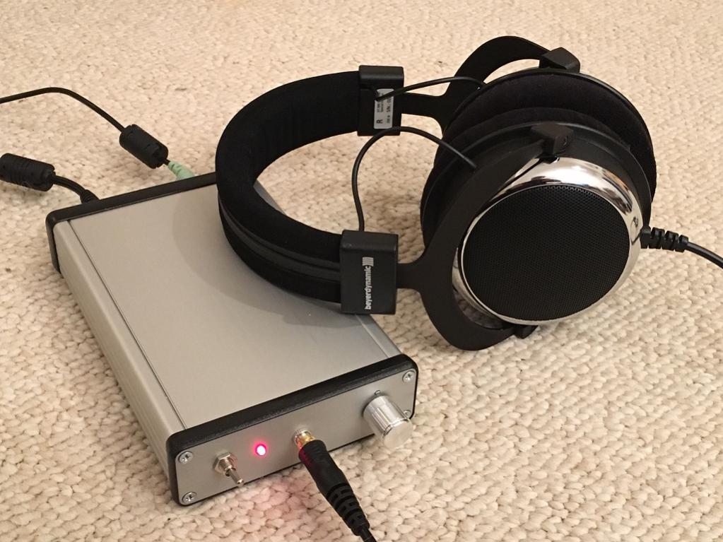
I am so jazzed about this I want to box it immediately so I can take it with me.
I am listening to stuff from my XMOS U8 DAC at 176kbit so that the detail can indeed come out.
Blue Rondo a la Turk, Take Five, Impressions of Toledo, Keith Don't Go, and a bunch of deep bass House dance mixes. All fantastic.
What does
mean? Xmas present?Chrissy pressie
Last edited:
X,
The CFH7 is an outstanding amp, but I have seen this before in the original Japanese and generally avoid symmetrical circuits. This is just my preference; I like single ended circuits, like your jfet HPA.
Accordingly, I would like the build the preamp for a headphone, though I have been examining the jfet circuit with HPA applications and it's range is very limited. I built one three years back using bipolar/mosfet CFP supplied from a smps at 48V and the sound was astonishingly good. I suspect your version is superior, so a build is on the cards......
The harmonic profile at 1Vp into a 280R headphone (I have a Beyerdynamic DT880 too) is typically H2 -55dB, H3 -79dB and H5 -86dB. This is very like the profile out of a plate loaded triode, and for the same reason because the topology is plate loaded directly connected to cathode follower. The transfer function of a tube, power 1.5, is quite similar to a jfet, power 2, so their distortions are similar. The great advantage of jfets is their quiet behaviour, low voltage and the lack of a filament! This is as close you get to a tube circuit without bottles, and I believe the
resolution is superior.
I have been simulating the source load for the second jfet. If you replace the bottom jfet and replace with 680R you lose nothing and you reduce the parts count. Most of the output voltage is driven from the first, voltage stage, so changing the bottom CCS with a resistor has no effect on the range. Whether it affects the SQ would be moot; I suspect not. It would increase the output current from 9mA to 12.5mA, giving a dissipation of 119mW using 18V supply (to be just within the 20V max on the datasheet).
At -6dB output (1.42Vpp into 280R) H2/H5 is -52dB/-85dB, close to a triode circuit, but not much more than 4Vpp output before the negative trough starts to badly distort.
This is a classic triode circuit, converted to jfet, with bad measurement figures, low dynamic range and limited drive but with celestial Sound Quality - harps on heaven stuff. It is proof positive that many of the variables we audiophiles use to assess quality are completely off the mark. There is clearly a lot of psychoacoustic stuff we do not measure.
Hugh
Last edited:
Hugh,
Are you talking about dropping the bottom BF862 on the preamp or the bottom LU1014D on the power amp stage to reduce parts count without affecting SQ? When you it has low dynamic range is that theoreamp stage or the power amp stage? The poweramp stage is running about 400mA bias righ now. I don't feel it has limited dynamic range on my DT880's.
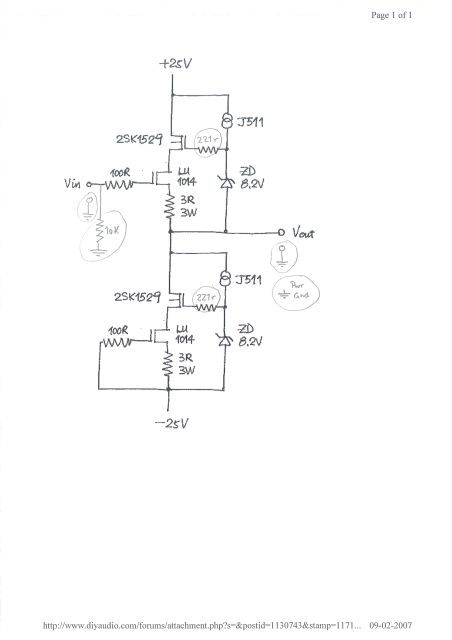
The power amp is based on this circuit, with J511 replaced by J310 and 470R in CCS mode and the 8.2Z replaced by 6.8Z and red LED, and IRFP240's for the 2SK1529 MOSFETs.
Are you talking about dropping the bottom BF862 on the preamp or the bottom LU1014D on the power amp stage to reduce parts count without affecting SQ? When you it has low dynamic range is that theoreamp stage or the power amp stage? The poweramp stage is running about 400mA bias righ now. I don't feel it has limited dynamic range on my DT880's.
The power amp is based on this circuit, with J511 replaced by J310 and 470R in CCS mode and the 8.2Z replaced by 6.8Z and red LED, and IRFP240's for the 2SK1529 MOSFETs.
Last edited:
Sorry, X, I'm talking only of the BF862..... the dynamic range (that is the max Vpp output) of the BF862 is about 4.5Vpp output.
However, your LU1014D circuit is interesting too.... question: do you need a 100R stopper on the two bases, because in my experience highish stoppers damage the music badly. What sort of beta do you have on these devices, I understand the beta is LOW on these. I have always been confused about WHY they are used in audio, their low beta, high base and speed issues make them suitable for power traction work, don't they? And they are EXPENSIVE.
Chrissie Pressie is Xmas present, as you guessed......
Hugh
The LU1014D is kind of unique in that it is a power JFET capable of huge currents. It's not expensive. Matched pairs for $6 I think. Unmatched for about $1.50 ea. I think they sound quite nice. I don't know why 100R used on gates other than to suppress potential instability. Maybe can be bypassed - can try easily. Do you expect SQ to improve as well?
http://www.amplimos.it/images/LU1014D.pdf
If you like the BF862 as a power amp - I did that too. Four pairs in parallel in SE mode. More here:
http://www.diyaudio.com/forums/head...f862-based-se-class-headamp-without-heat.html
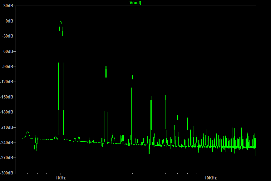
Predicted FFT as built:
Sounds quite nice but can't match the dynamics of the title HA.
http://www.amplimos.it/images/LU1014D.pdf
If you like the BF862 as a power amp - I did that too. Four pairs in parallel in SE mode. More here:
http://www.diyaudio.com/forums/head...f862-based-se-class-headamp-without-heat.html
Predicted FFT as built:
Sounds quite nice but can't match the dynamics of the title HA.
Last edited:
Hugh,
> However, your LU1014D circuit is interesting too....
May I clarify for you of the origin of these circuits posted here.
The LU1014 Follower being posted here and elsewhere originated from me in 2007.
http://www.diyaudio.com/forums/head...follower-headphone-amplifier.html#post1130805
It has long been superceeded by later versions.
http://www.diyaudio.com/forums/head...se-all-fet-class-zgf-headphone-amplifier.html
You can find detailed published information of those circuits in the original threads.
The SRPP + White Follower was originally from easphyx
http://www.diyaudio.com/forums/solid-state/298026-tin-fets-headphone-amplifier.html
The BF862 version was posted by me at the same thread, for the sake of exchange of circuit ideas.
http://www.diyaudio.com/forums/solid-state/298026-tin-fets-headphone-amplifier.html#post4895179
I did not, and shall not build because I don't build amps with decoupling caps.
Cheers,
Patrick
Last edited:
Hugh,
> However, your LU1014D circuit is interesting too....
May I clarify for you of the origin of these circuits posted here.
The LU1014 Follower being posted here and elsewhere originated from me in 2007.
http://www.diyaudio.com/forums/head...follower-headphone-amplifier.html#post1130805
It has long been superceeded by later versions.
http://www.diyaudio.com/forums/head...se-all-fet-class-zgf-headphone-amplifier.html
You can find detailed published information of those circuits in the original threads.
The SRPP + White Follower was originally from easphyx
http://www.diyaudio.com/forums/solid-state/298026-tin-fets-headphone-amplifier.html
The BF862 version was posted by me at the same thread, for the sake of exchange of circuit ideas.
http://www.diyaudio.com/forums/solid-state/298026-tin-fets-headphone-amplifier.html#post4895179
I did not, and shall not build because I don't build amps with decoupling caps.
Cheers,
Patrick
Don't worry EUVL - I credited you with all this in the first post of this thread if you had bothered to read. You wanted me off your threads and said you wanted nothing to do with my builds because heaven forbid, I don't match my JFETs. So now I am here in a different thread. Why follow me then?
Patrick,
Thank you for comments and the origins.
I cannot understand why you do not build amps with decouplers; why?
If you claim a circuit either patent it or tell no one. You cannot publish here and then expect ownership; publishing legally defines public domain. XRK has done outstanding builds here which are both real, working designs and has given the benefits of his prodigious output and his subjective assessments whilst being open to ideas from others. The subjective assessments are incredibly important.
I was involved with many other designs in this forum and helped do the layout and the schematic and it is completely public domain and no longer a part of my private IP. People like Alex MM, Juma, Prasi, Sonal and Idefixe are wonderful resource for this forum for their designs and layouts and it's what we are here for. I have other designs but I never discuss them in the forum as they are IP and sold commercially. You might wekk look at NP's and his marvellous approach. You never see any conflict about his work.
Thank you for your work.
HD
Last edited:
Sorry, X, I'm talking only of the BF862..... the dynamic range (that is the max Vpp output) of the BF862 is about 4.5Vpp output.
Hugh,
Would three 2SK170BL's in a similar configuration have more dynamic range than the BF862's? Maybe I need to just simulate in LTSpice and find out. I can easily make the same circuit in through hole components with TO92's.
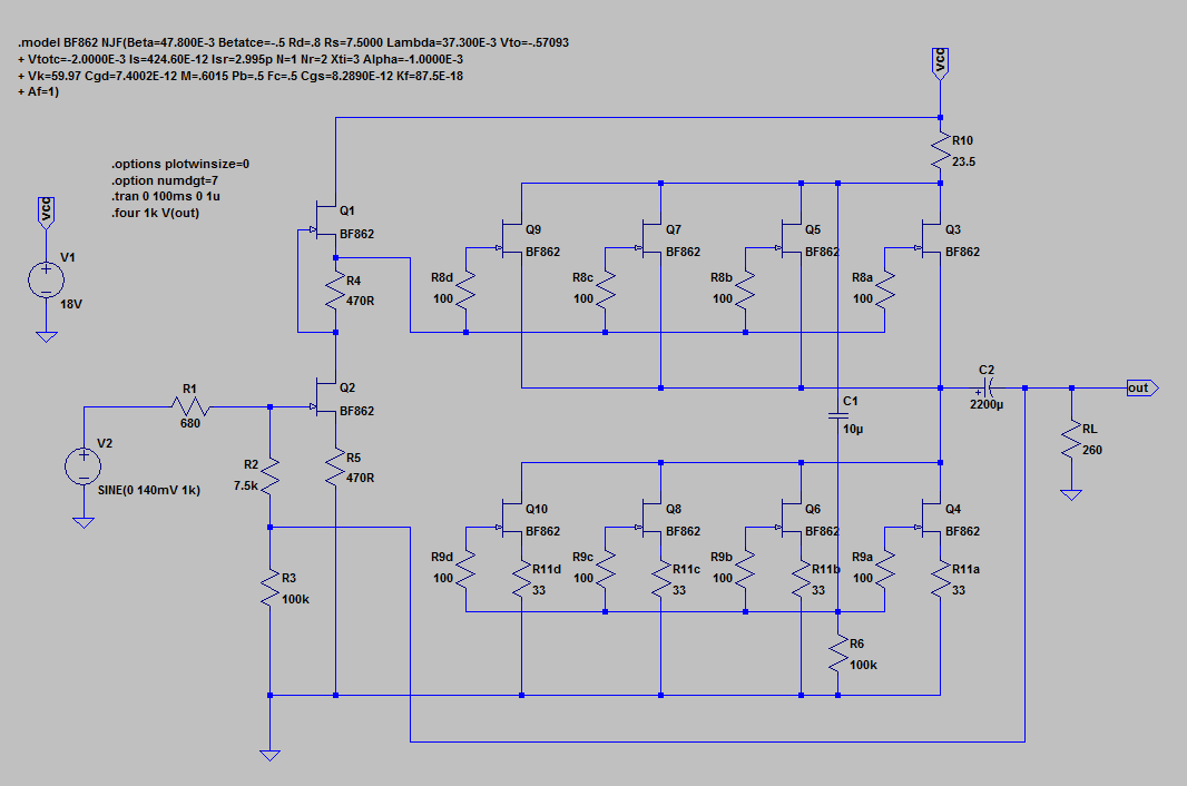
LTSpice of the dual JFET HPA
Hi XRK,
I have appended the LTSpice analysis of the preamp, using two jfets, deleting the jfet CCS which adds very little to the harmonic profile or THD.
I will examine it with a few more jfets to drive the output directly to the 280R headphone. I make it around 25R Zout with a single jfet; this might improve it.
I can see why it sounds good.... THD at 1.42Vpp output (-6dBU) with a gain of 8.9dB is 0.252% and 99.75% of this is H2, adding warmth aplenty AND masking the higher harmonics.
Seems we like H2, huh?
Hugh
Attachments
Better Performance
Hi XRK,
With three parallel BF862s, all matched and running each at 12.6mA, you do get superior performance. Clip rises from 4.8Vpp to 7.3Vpp, a useful increase, but significantly much less distortion though the profile is maintained.
Appended, you can compare very well. Speed is down, since drive is much the same, but still more than enough for up to 13Mhz, the 1dB upper point. Note that operating points are the same; but the load resistor, now 220R, dissipates 315mW so it would need to be a 1W metal film. Matching would be essential; BUT you could put in 22R source resistors on each but it would increase Zout a little. As it is, Zout is around 12R, low enough for 80R cans.
Hugh
Attachments
Last edited:
Hugh,
This is indeed a very sweet find! A 4 JFET headamp with tube like sound and only H2
I will certainly make this Juma pre-amp on steroids - and it will fit an Altoids tin nicely with two 9v batts in series for 18v! 47uF output cap can be small Panasonic OSCON. I happen to to have a bunch of 330uF's lying around that may boost the bass?
Thanks for the sim!
Too bad I don't have a laserprinter at home or I would make it right now.
****
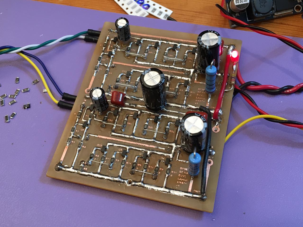
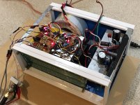
On the Title thread subject amp, I made good progress with a 3d jigsaw puzzle to stuff the trafo, PSU, cap Mx, LC cap bank, 2 power amps with heatsinks, a fan, and a preamp into a tiny (10in x 7.5in x 4.3in) steel case. Nothing fancy and no milled aluminum faceplates or visible fins on this guy. A very unassuming box with powerful sound. I did a layout test with components in actual locations inside box to see if noise pickup would be an issue. Hum from trafo to amp etc. Great news: no noise and it sounds great still.
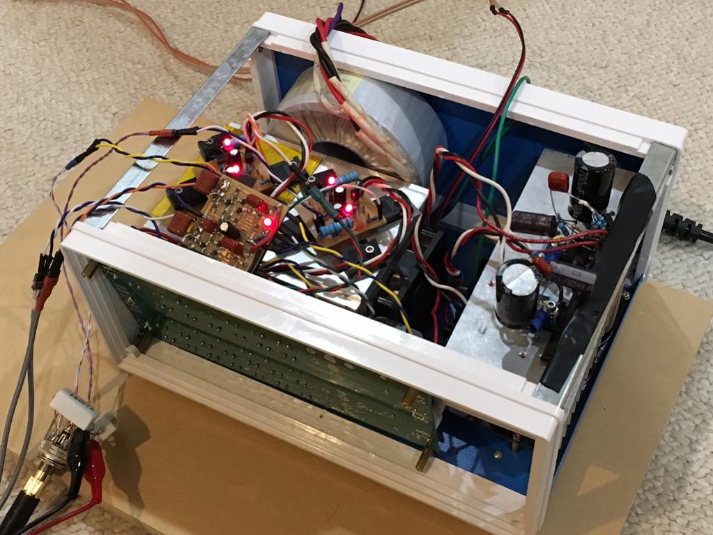
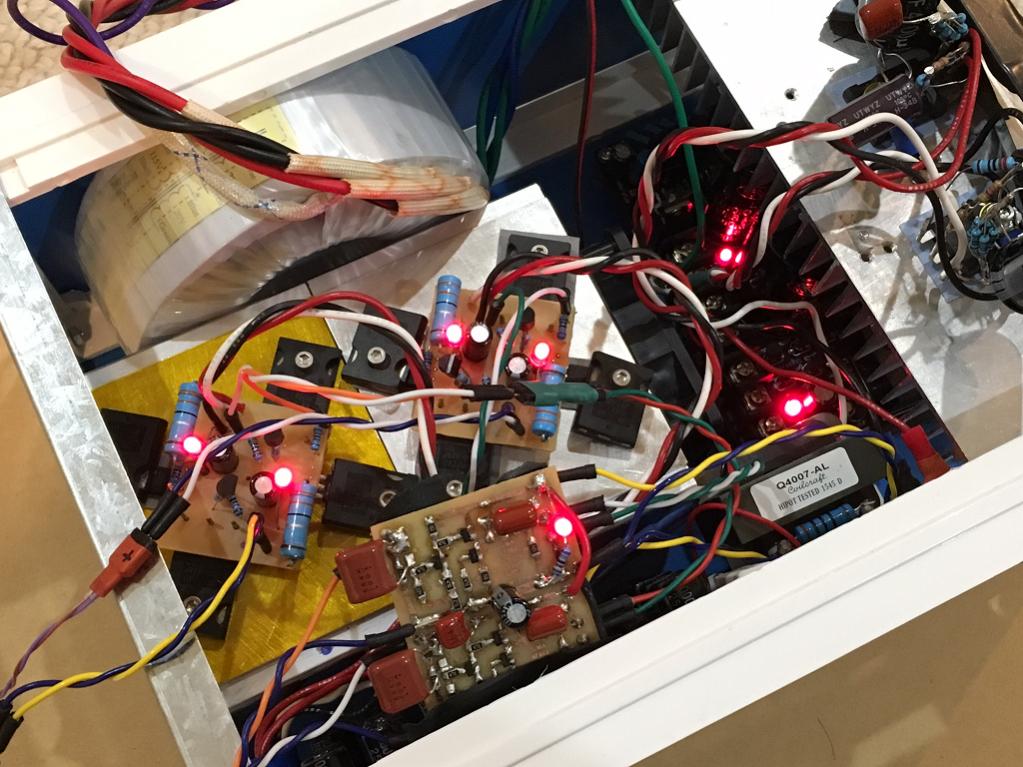
So one step closer to a boxed amp. Holes will be drilled in stages and I need to use nibbler tool to cut rectangular IEC receptacle (those are a pain). The cap Mx will be bolted directly to rear panel - no fins. Should be fine at 400mA x 4v x 2 = 3.2w (a night-light in heat output).
A small 60mm fan running at reduced speed via a 100R power resistor for silent operation does wonders on reduction of fin footprint.
Probably considered blasphemy for some to put the ultimate class A headamp in a cheap $19 case sans external fins or CNC'd fascia plate.
This is indeed a very sweet find!
A 4 JFET headamp with tube like sound and only H2 I will certainly make this Juma pre-amp on steroids - and it will fit an Altoids tin nicely with two 9v batts in series for 18v! 47uF output cap can be small Panasonic OSCON. I happen to to have a bunch of 330uF's lying around that may boost the bass?
Thanks for the sim!
Too bad I don't have a laserprinter at home or I would make it right now.
****
On the Title thread subject amp, I made good progress with a 3d jigsaw puzzle to stuff the trafo, PSU, cap Mx, LC cap bank, 2 power amps with heatsinks, a fan, and a preamp into a tiny (10in x 7.5in x 4.3in) steel case. Nothing fancy and no milled aluminum faceplates or visible fins on this guy. A very unassuming box with powerful sound. I did a layout test with components in actual locations inside box to see if noise pickup would be an issue. Hum from trafo to amp etc. Great news: no noise and it sounds great still.
So one step closer to a boxed amp. Holes will be drilled in stages and I need to use nibbler tool to cut rectangular IEC receptacle (those are a pain). The cap Mx will be bolted directly to rear panel - no fins. Should be fine at 400mA x 4v x 2 = 3.2w (a night-light in heat output).
A small 60mm fan running at reduced speed via a 100R power resistor for silent operation does wonders on reduction of fin footprint.
Probably considered blasphemy for some to put the ultimate class A headamp in a cheap $19 case sans external fins or CNC'd fascia plate.
Attachments

Last edited:
- Home
- Amplifiers
- Headphone Systems
- MOSFET Source Follower Headamp