Good prices but many fake parts!Very good price.
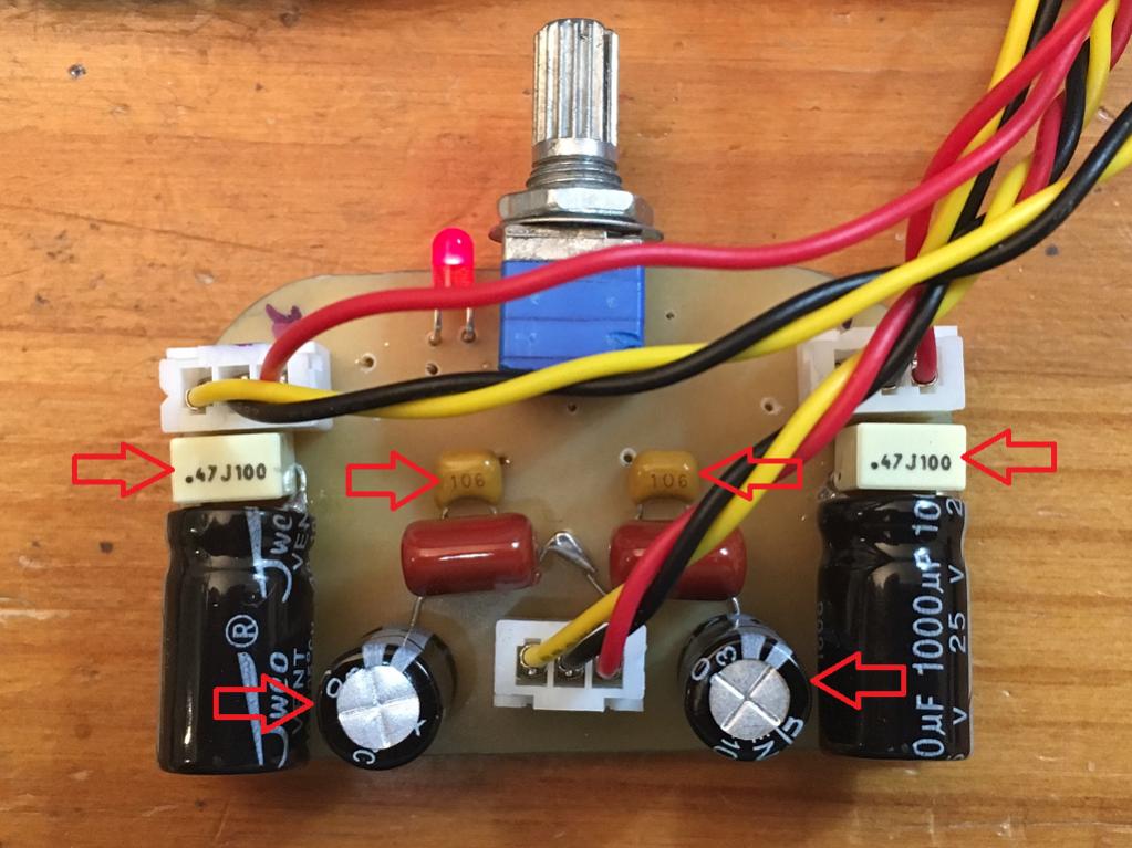
I put this 2 JFET amp in a case quickly so that I can take it with me out of the lab to enjoy music outside the lab. I am using a 24v 5amp SMPS, a Juma cap multiplier, and qnty 16 x 2200uF 25v cap bank for 35mF, that cap bank is connected via 0.33R to 5 x 2200uF cap bank 11mF after the 4700uF cap connected to the Mx. The 16 cap bank has 3.1mOhm ESR - this is good because it about matches the Rdson of the LU1014D for unmitigated bass authority.The 50k volume pot is mounted on a bare veroboard for addition of future cross-feed filter.
Hi X,
Is this how you connect the cap bank?
SMPS -> Mx -> 11mF -> 0.33R -> 35mF cap bank
I don't speak about bf862 but i see lm4562 for 1$ ,10x2sk170BL for 2$ e.t.cI don't think anyone is going to bother faking a SOT23 BF862 at nominal $0.60ea.
I put this 2 JFET amp in a case quickly so that I can take it with me out of the lab to enjoy music outside the lab. I am using a 24v 5amp SMPS, a Juma cap multiplier, and qnty 16 x 2200uF 25v cap bank for 35mF, that cap bank is connected via 0.33R to 5 x 2200uF cap bank 11mF after the 4700uF cap connected to the Mx. The 16 cap bank has 3.1mOhm ESR - this is good because it about matches the Rdson of the LU1014D for unmitigated bass authority.
Hi X,
Is this how you connect the cap bank?
SMPS -> Mx -> 11mF -> 0.33R -> 35mF cap bank
Almost, I forgot to mention that there is a 0.47R between CMx and 11mF for additional filtering.
SMPS --> CMx w/ 4700uF --> 0.47R --> 11mF --> 0.33R --> 33mF
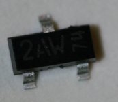
I just bought 20 of each too.Can you read the code on the package?
Attachments
The other mosfet circuit with the ZVN4306 could be run at a simple source follower, with gate stopper of 100R from the drain of the previous BF862 first stage.
I will do some sims on this both with passive resistor loading, and CCS.
Hugh
Hi Hugh,
Have you had a chance to sim the ZVN4306 MOSFET as source follower?
Thanks,
X
Almost, I forgot to mention that there is a 0.47R between CMx and 11mF for additional filtering.
SMPS --> CMx w/ 4700uF --> 0.47R --> 11mF --> 0.33R --> 33mF
first I use 2 x Muse BP 1000uf 25V on the CapMx and sound very nice.
Then REPLACE THE 2 MUSE WITH ONE 2200UF 50v ON THE cAPmX
smps ->capmX 2200UF -> 6X 2200Uf -> 4X 1R -> 4X 3300UF 50v
After adding the cap bank,the highs are good but not as sweet as the BP Muse.
X,
I do not have the model; and in fact not sure how to absorb into LTSpice when I get it.....
Cheers,
Hugh
Zetex publishes their models - I an not sure if it's as simple as pasting relevant code into schematic ?
http://espice.ugr.es/espice/src/modelos_subckt/ZMODELS.LIB
*ZETEX ZVN4306 Spice model Last revision 3/92
*
.SUBCKT ZVN4306 30 40 50
*NODES: DRAIN GATE SOURCE
M1 30 20 50 50 MOD1
RG 40 20 108
RL 30 50 6E6
D1 50 30 DIODE1
.MODEL MOD1 NMOS VTO=2.634 RS=0.2762 RD=0.0 IS=1E-15 KP=9.77
+CGSO=224.5E-12 CGDO=10.5E-12 CBD=405E-12 PB=1 LAMBDA=0
.MODEL DIODE1 D IS=6.19E-13 N=1.0043 RS=0.065
.ENDS ZVN4306
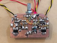
I am working on a slick little Altoids tin amp board using the ZVN4306 and BF862. I need to figure out values in order to set bias on MOSFET correctly - I am aiming for circa 60mA.
Here is half of the layout using a sharpie marker.
Attachments
Last edited:
Thanks X!
I have come to the conclusion after examinining Elfishi's schematic with dissimilar BF862s that there is not much point using 10R source resistors. The distortion is no better, and the Zout is higher. Always best to match the BF862s for idss within 5%, that is good enough.
I will fiddle with this ZVN4306 later today...... thank you for sending them on.
Hugh
Zetex publishes their models - I an not sure if it's as simple as pasting relevant code into schematic?
As far as my experience goes, no. I had to create dedicated ZTX**** schematic symbols and point them to the model (in my SUB folder) to get my simulations to work. Perhaps there is another way, though, that I did not try.
At any rate, the .subckt is harder to use than the .model.
Pocket Class A First Sound
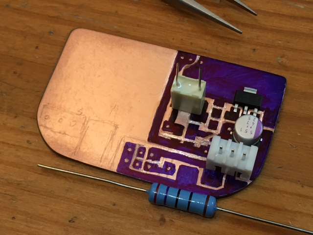
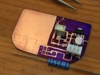
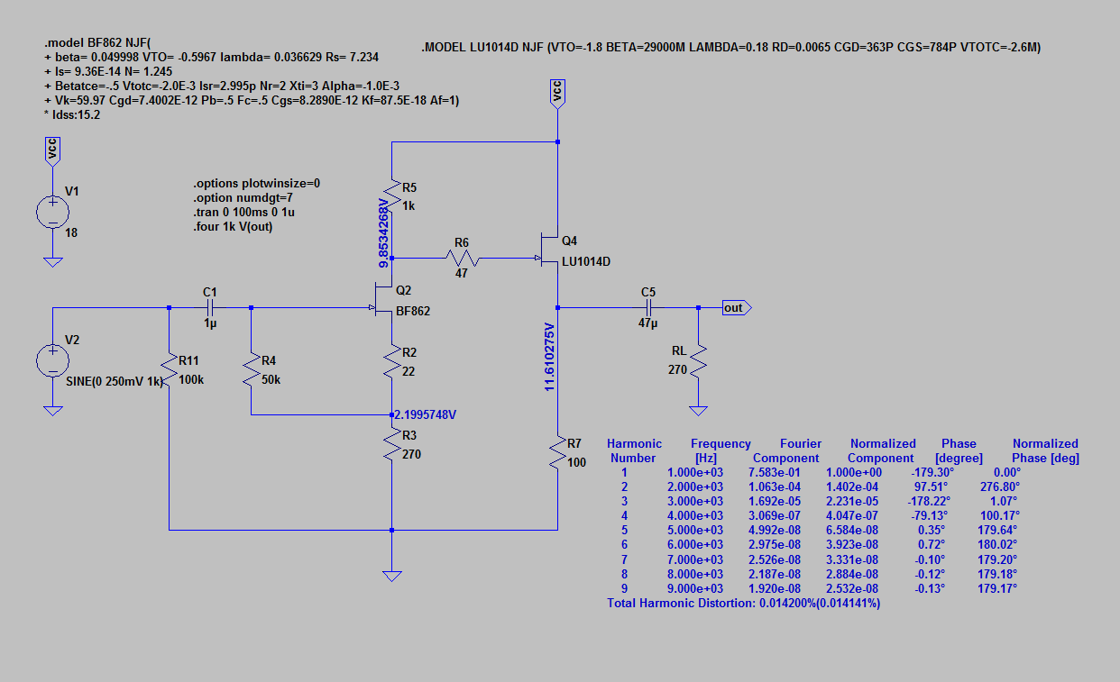
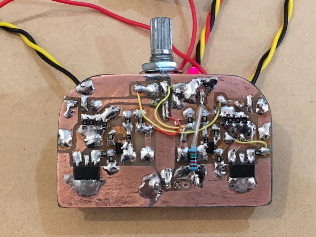
Well, I had a productive night. The BF862 and ZVN4306 amp is now singing. I had to adjust the input source resistor to 100R to get enough voltage at the gate of the MOSFET. I am running qnty 4 x 470R SMT source resistors in parallel (123R) on the ZVN MOSFET for a bias current of 67mA. I left a lot of copper plane for a heatsink for the MOSFETs.
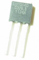
Circuit follows this schematic but with LU1014D replaced with ZVN4036 SOT-23 but with R2=100R and R7=123R, R6 = 220R, and output C is 1000uF:
The SMT parts on on one side, which I will put in thermal contact with the bottom of the case. The through hole components are on top and will be visible,
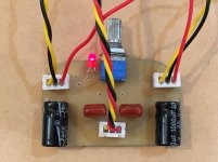
Just tested a few songs - sounds very promising - nice bass, clear highs, smooth mids. Running from two 9v Li-ion batteries in series for 18v supply.
The board has been tested to fit in an Altoids tin with two 9v batteries perfectly.
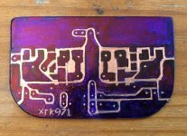
Final layout before acid etch:

SMT side (I wanted to use nice 47uF OSCONs but change of plans put SMT on flat side next to case so no room):
Top side:

First sound test:
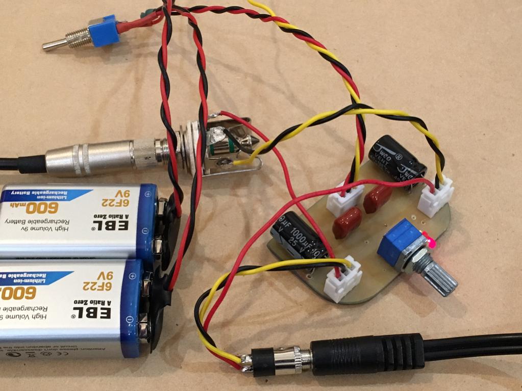
It's running now and temperatures are doing OK - not too hot. Sound is very nice.
Zetex publishes their models - I an not sure if it's as simple as pasting relevant code into schematic ?
http://espice.ugr.es/espice/src/modelos_subckt/ZMODELS.LIB
I am working on a slick little Altoids tin amp board using the ZVN4306 and BF862. I need to figure out values in order to set bias on MOSFET correctly - I am aiming for circa 60mA.
Here is half of the layout using a sharpie marker.
Well, I had a productive night. The BF862 and ZVN4306 amp is now singing. I had to adjust the input source resistor to 100R to get enough voltage at the gate of the MOSFET. I am running qnty 4 x 470R SMT source resistors in parallel (123R) on the ZVN MOSFET for a bias current of 67mA. I left a lot of copper plane for a heatsink for the MOSFETs.
Circuit follows this schematic but with LU1014D replaced with ZVN4036 SOT-23 but with R2=100R and R7=123R, R6 = 220R, and output C is 1000uF:
The SMT parts on on one side, which I will put in thermal contact with the bottom of the case. The through hole components are on top and will be visible,
Just tested a few songs - sounds very promising - nice bass, clear highs, smooth mids. Running from two 9v Li-ion batteries in series for 18v supply.
The board has been tested to fit in an Altoids tin with two 9v batteries perfectly.
Final layout before acid etch:
SMT side (I wanted to use nice 47uF OSCONs but change of plans put SMT on flat side next to case so no room):
Top side:
First sound test:
It's running now and temperatures are doing OK - not too hot. Sound is very nice.
Attachments

Last edited:
Skylab,
What amp are you listening to?
I am testing it ony 3116 and the F5HA.
Some more mods with caps and resistors which improved clarity and bass extension:
http://www.diyaudio.com/forums/head...lass-headamp-without-heat-11.html#post4944606

Superb sound - wonderful bass and clarity now.
http://www.diyaudio.com/forums/head...lass-headamp-without-heat-11.html#post4944606
Superb sound - wonderful bass and clarity now.
I wanted to use nice 47uF OSCONs but change of plans put SMT on flat side next to case so no room
X, have you looked at the Panasonic CT / CX series? Also polymer but in a much smaller package (7.3 x 4.3 x 1.9mm), and decent voltages
https://industrial.panasonic.com/cdbs/www-data/pdf/ABE0000/ABE0000C49.pdf
X, have you looked at the Panasonic CT / CX series? Also polymer but in a much smaller package (7.3 x 4.3 x 1.9mm), and decent voltages
https://industrial.panasonic.com/cdbs/www-data/pdf/ABE0000/ABE0000C49.pdf
Thanks for the tip! I will have to pick some up on my next order of parts.
- Home
- Amplifiers
- Headphone Systems
- MOSFET Source Follower Headamp