Hi Kees,
Good to hear from you. You should try one of these pocket head phone amps. They don't use feedback which I know you like.
Cheers,
X
Thanks for the advise X but I go speaker, I like that more also.
I have current feedback when I use it, but need to learn more to get ltspice measure HD better, I did see the voltage source already has -60 dB distance, but need to be -120 or so.
I was busy with mother who is 86 has broke a bone.
regards
This thread seems to be the place for technical discussion of X's amps, so I'll post this here rather than the GB page.
Since I want to try more cap rolling in my Pocket Class A, I decided to educate myself on the subject of capacitors for audio. I found many subjective impressions of different caps, some quite interesting. Then after a bit of research, I stumbled upon what many refer to as the definitive resource on the subject--Cyril Bateman's "Capacitor Sounds" articles. Bateman basically did extensive FFT measurements of many different capacitors to quantify their distortion. Below is my "Cliff's Notes" summary of the six-part, 80 page series. Please correct me if I post any nonsense.
…………………………………………………………
1. Capacitor distortion does not correlate with dissipation factor or ESR, but rather with dielectric absorption. Bateman's tests suggest that dielectric absorption is in fact the main cause of capacitor distortion.
2. An electrolytic cap's THD (especially H2) increases with DC bias voltage. An electrolytic cap biased at 50% of its voltage rating produces 6 times more THD than the same cap biased at just 10% of its rating. This substantiates the popular belief that between two caps of identical material and capacitance, the cap with the higher voltage rating sounds better.
3. Electrolytic caps produce a nearly fixed amount of IMD, H3 and higher order distortion. Again, only H2 increases (dramatically) with increased DC bias voltage. Biased at 10% of the cap's voltage rating, H2 is at such a minimum level that H3 dominates (yuck!). Biased at 20% of the voltage rating, H2 rises to equal H3, and and at all higher voltages beyond 20% of the rating, H2 dominates.
4. Bi-polar electrolytic caps distort half as much as their polar counterparts, and have less dielectric absorption too. Too bad they're big!
5. A film bypass with with an electrolytic cap can reduce distortion,--larger bypasses more effectively so. A bypass with a capacitance of 10% of the main electrolytic proved marginally effective at reducing distortion, while a bypass with just 1% of the main cap's value yielded an insignificant reduction.
6. Film caps distort far less than electrolytics. A PET cap distorts 1/6 as much an optimally-biased polar electrolytic cap of the same capacitance, and 1/3 as much as a bi-polar electrolytic cap.
7. Polypropylene film caps distort less than polyesters. An unbiased 0.1 uF WIMA MKS metallised PET cap distorted 2x as much as a 0.1uF WIMA FKP foil/PP cap and introduced significant IMD to the signal. When biased at 18v, the MKS distorted 28x as much as the FKP cap! Bateman says that larger capacitance PET caps perform much better than these tiny ones though.
8. Foil/film caps distort less than metallised film caps. The #7 comparison isn't quite fair. Even polyester performs decently with a foil electrode. The WIMA FKS foil/PET series measured "almost as good" as WIMA FKP2 (Bateman's words in quotes, no direct comparisons were published). Hooray for foil.
9. COG ceramic disc caps distort thousands of times less than X7R ceramics. Bateman's XR7 cap test produced the scariest FFT I've ever seen! THD of .48%, 8000 times the distortion of the COG ceramic cap.
10. Other excellent dielectric options exist. Polycarbonate and polystyrene caps have very low distortion but are hard to find. Polyphenylene Sulphide caps are worth consideration: with a footprint only slightly larger than metallised PET, PPS caps distort almost as little as polypropylene caps.
…………………………………………………………
When considering the Pocket Class A amp in particular, I am struck by the fact that portable amps must make concessions in order to achieve an acceptably small form factor. Electrolytic and polyester caps are the only options that will fit in an Altoids tin and provide the needed values.
Here's what I want to know:
How much of the Pocket Class A's THD is contributed by capacitors in the signal path?
I think I could make a *very* rough estimate using some of Bateman's measurements of caps similar to what we are using, IF I knew the bias voltage of the amp. Sadly, although I have built one, I do not know! Noob alert!
Help me out here, X!
Since I want to try more cap rolling in my Pocket Class A, I decided to educate myself on the subject of capacitors for audio. I found many subjective impressions of different caps, some quite interesting. Then after a bit of research, I stumbled upon what many refer to as the definitive resource on the subject--Cyril Bateman's "Capacitor Sounds" articles. Bateman basically did extensive FFT measurements of many different capacitors to quantify their distortion. Below is my "Cliff's Notes" summary of the six-part, 80 page series. Please correct me if I post any nonsense.
…………………………………………………………
1. Capacitor distortion does not correlate with dissipation factor or ESR, but rather with dielectric absorption. Bateman's tests suggest that dielectric absorption is in fact the main cause of capacitor distortion.
2. An electrolytic cap's THD (especially H2) increases with DC bias voltage. An electrolytic cap biased at 50% of its voltage rating produces 6 times more THD than the same cap biased at just 10% of its rating. This substantiates the popular belief that between two caps of identical material and capacitance, the cap with the higher voltage rating sounds better.
3. Electrolytic caps produce a nearly fixed amount of IMD, H3 and higher order distortion. Again, only H2 increases (dramatically) with increased DC bias voltage. Biased at 10% of the cap's voltage rating, H2 is at such a minimum level that H3 dominates (yuck!). Biased at 20% of the voltage rating, H2 rises to equal H3, and and at all higher voltages beyond 20% of the rating, H2 dominates.
4. Bi-polar electrolytic caps distort half as much as their polar counterparts, and have less dielectric absorption too. Too bad they're big!
5. A film bypass with with an electrolytic cap can reduce distortion,--larger bypasses more effectively so. A bypass with a capacitance of 10% of the main electrolytic proved marginally effective at reducing distortion, while a bypass with just 1% of the main cap's value yielded an insignificant reduction.
6. Film caps distort far less than electrolytics. A PET cap distorts 1/6 as much an optimally-biased polar electrolytic cap of the same capacitance, and 1/3 as much as a bi-polar electrolytic cap.
7. Polypropylene film caps distort less than polyesters. An unbiased 0.1 uF WIMA MKS metallised PET cap distorted 2x as much as a 0.1uF WIMA FKP foil/PP cap and introduced significant IMD to the signal. When biased at 18v, the MKS distorted 28x as much as the FKP cap! Bateman says that larger capacitance PET caps perform much better than these tiny ones though.
8. Foil/film caps distort less than metallised film caps. The #7 comparison isn't quite fair. Even polyester performs decently with a foil electrode. The WIMA FKS foil/PET series measured "almost as good" as WIMA FKP2 (Bateman's words in quotes, no direct comparisons were published). Hooray for foil.
9. COG ceramic disc caps distort thousands of times less than X7R ceramics. Bateman's XR7 cap test produced the scariest FFT I've ever seen! THD of .48%, 8000 times the distortion of the COG ceramic cap.
10. Other excellent dielectric options exist. Polycarbonate and polystyrene caps have very low distortion but are hard to find. Polyphenylene Sulphide caps are worth consideration: with a footprint only slightly larger than metallised PET, PPS caps distort almost as little as polypropylene caps.
…………………………………………………………
When considering the Pocket Class A amp in particular, I am struck by the fact that portable amps must make concessions in order to achieve an acceptably small form factor. Electrolytic and polyester caps are the only options that will fit in an Altoids tin and provide the needed values.
Here's what I want to know:
How much of the Pocket Class A's THD is contributed by capacitors in the signal path?
I think I could make a *very* rough estimate using some of Bateman's measurements of caps similar to what we are using, IF I knew the bias voltage of the amp. Sadly, although I have built one, I do not know!
Noob alert!Help me out here, X!
You're right. I think Bateman's tests do confirm this effect, to a point. As I recall, some capacitors needed a minimum amount of bias to keep them linear. But above that minimum, distortion still increases with bias voltage. I'll have to look back to see which caps this effect applies to.
Bateman seems to believe that optimal bias for an electro is at or below 10% of the cap's rating, where THD is minimized. I think that fans of the H2 dominant sound might disagree, and will probably prefer something above 20%, where H2 dominates H3. Still, Bateman's tests make a pretty good case for not exceeding 50% of rating... This makes me glad that I accidentally ordered 25V output caps, when 16v would seem adequate based on just the manufacturer specs.
Bateman seems to believe that optimal bias for an electro is at or below 10% of the cap's rating, where THD is minimized. I think that fans of the H2 dominant sound might disagree, and will probably prefer something above 20%, where H2 dominates H3. Still, Bateman's tests make a pretty good case for not exceeding 50% of rating... This makes me glad that I accidentally ordered 25V output caps, when 16v would seem adequate based on just the manufacturer specs.
Last edited:
nice post!You're right. I think Bateman's tests do confirm this effect, to a point. As I recall, some capacitors needed a minimum amount of bias to keep them linear. But above that minimum, distortion still increases with bias voltage. I'll have to look back to see which caps this effect applies to.
Bateman seems to believe that optimal bias for an electro is at or below 10% of the cap's rating, where THD is minimized. I think that fans of the H2 dominant sound might disagree, and will probably prefer something above 20%, where H2 dominates H3. Still, Bateman's tests make a pretty good case for not exceeding 50% of rating... This makes me glad that I accidentally ordered 25V output caps, when 16v would seem adequate based on just the manufacturer specs.
Trying to answer my own questions... I remembered that X posted this in the PCA Head-Fi thread:
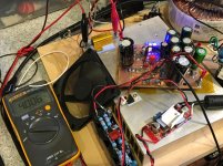
Check your bias current across the R7 array of four resistors. Measure voltage at pin 3 of the MOSFETs. It should be at least 5.7v with a fresh set of batteries. 5.7v divided by 117.5ohms is about 50mA (49mA actually) As batteries wear out it will drop a bit.
If bias is only 5.8v, a 16V output electrolytic is probably biased right at its sweet spot for H2 dominance without too much.
But I am still not sure if this is the bias voltage seen by the caps, because in post #151 of the GB thread X said:
"my cheap JWCO 2200uF 16v caps measure in at 250mOhm at 120z - not too bad. Those are safe to use as outputs because the DC level there is circa 8v to 11v."
So maybe it is as high as 11V?
Whatever you measure at the output of the MOSFET is the DC voltage. The AC swings due music can be as high as the rail voltage minus the droput through the MOSFET (2 to 3v). So no more than 14v peak.
Two Li-ion batteries is 16.8v max. Typically drops to 16.4v immediately under load. Within 10'inutes is 16v or less.
Two Li-ion batteries is 16.8v max. Typically drops to 16.4v immediately under load. Within 10'inutes is 16v or less.
bias
The DC bias voltage across the cap is very simply the DC voltage measured at the input side of the cap. The output side will be zero. Turn the amp on, measure the DC voltage at the junction of the cap and the MOSFET source, and that's the voltage. The AC will ride on top of (and below that) voltage. In fact, if you measure the DC voltage while playing music you will see that it does not change (or by very, very little).
Let's say you have an 18V unipolar supply and the junction of the cap/MOSFET source pin is 9V. The cap's DC bias is 9V, and the max AC voltage is 18Vpp. If the junction is sitting at 10V, the max AC voltage drops to 16Vpp. Now in reality, you won't get 18Vpp or 16Vpp, for other reasons. But "in the middle" gives the best possibility. But that doe not change the DC voltage that will always be present on one side of the cap.
With (most) unipolar power supply designs the voltage is typically fixed at 1/2 Vcc. That is a conscious choice made by the designer which gives the max AC voltage.
But, consider for a moment a bipolar design. You now have 2 rails, usually of equal value, and you know that obtaining largest AC swing requires placing the cap voltage around 0V. With a bipolar design you'll be intentionally biasing the DC voltage across the cap at very close to 0V. I am currently playing with a bipolar BJT compound follower, and the DC voltage at the cap is -0.6V.
You could try a bipolar supply for you pocket amp and see if you can hear a difference. We each have our subjective opinions, fewer have objective facts, but at the end of the day they are your ears.
But I am still not sure if this is the bias voltage seen by the caps...
The DC bias voltage across the cap is very simply the DC voltage measured at the input side of the cap. The output side will be zero. Turn the amp on, measure the DC voltage at the junction of the cap and the MOSFET source, and that's the voltage. The AC will ride on top of (and below that) voltage. In fact, if you measure the DC voltage while playing music you will see that it does not change (or by very, very little).
Let's say you have an 18V unipolar supply and the junction of the cap/MOSFET source pin is 9V. The cap's DC bias is 9V, and the max AC voltage is 18Vpp. If the junction is sitting at 10V, the max AC voltage drops to 16Vpp. Now in reality, you won't get 18Vpp or 16Vpp, for other reasons. But "in the middle" gives the best possibility. But that doe not change the DC voltage that will always be present on one side of the cap.
With (most) unipolar power supply designs the voltage is typically fixed at 1/2 Vcc. That is a conscious choice made by the designer which gives the max AC voltage.
But, consider for a moment a bipolar design. You now have 2 rails, usually of equal value, and you know that obtaining largest AC swing requires placing the cap voltage around 0V. With a bipolar design you'll be intentionally biasing the DC voltage across the cap at very close to 0V. I am currently playing with a bipolar BJT compound follower, and the DC voltage at the cap is -0.6V.
You could try a bipolar supply for you pocket amp and see if you can hear a difference. We each have our subjective opinions, fewer have objective facts, but at the end of the day they are your ears.
Maybe this is OT but I am developing a desktop amp that indeed does put out the HEAT.
SE pure Class A topology with 3 actives in the signal path. There is a cap multiplier and a CCS so there are 5 actives total. JFET and MOSFETs and 1 BJT. Design will be for 32v rail and 70w total dissipation per channel whether music playing or not. Design goal of 4w into 50ohm cans or 10w into 8ohm speakers.
Currently under long term stress testing at 2w into 8ohm load. Also FFT monitoring and all looks great. THD still below 0.3% at 2w ito 8ohms. Super compact but as shown here needs a fan for such a compact heatsink. The sound is exquisite - same as my pocket Class A but on steroids given the 1.5amp bias (that's 1500mA !) for headphones.
Challenge was to make an amp that can drive HE1000's admirably.
Attachments
Last edited:
Mlackey, thanks for trying to help me measure these voltages myself. I'm sorry to be dense, but could somebody specify exactly which pin of the MOSFET and which lead of the cap I should probe with my multimeter? I got different readings depending on where I probed. I really have zero basic understanding of circuits. 
Thanks, X. So, DC bias is 6V and AC signal is 14V max. Is there an RMS value for the AC signal, or does it just stay right below 14V? Bateman showed that increased signal voltage raises distortion levels too, like bias does. There are a lot of variables and limited tests that he did, but I'm still interested in using his data to estimate cap distortion for this amp.
Thanks, X. So, DC bias is 6V and AC signal is 14V max. Is there an RMS value for the AC signal, or does it just stay right below 14V? Bateman showed that increased signal voltage raises distortion levels too, like bias does. There are a lot of variables and limited tests that he did, but I'm still interested in using his data to estimate cap distortion for this amp.
Pin 3 from left (farthest right) is the "Source" pin. Current flows from "Drain" to "Source" (yes it seems backwards unless you think of it as electrons (-ve) flowing). The AC signal is more like 0.3v to 1.5v for typical listening levels. I gave you absolute extremes and probably no more than 5v AC really. So Source of MOSFET is connected to R7 array, so whatever the DC level is here is same as imposed onto the output cap upstream side. Using Ohm's law V=IR, I=V/R. R is 117.5ohms (4 x 470R in parallel) so for say, 6.5v/117.5ohms is 55.3mA.
That helped!
I measure 6.5V DC bias and a steady 3.5V AC Signal (which happens to be Norah Jones). This is with a pair of dollar store batteries that have about two hours of runtime on them (each cell measuring 7.5V each at the moment).
Epic post coming soon. I think. lol
I measure 6.5V DC bias and a steady 3.5V AC Signal (which happens to be Norah Jones
). This is with a pair of dollar store batteries that have about two hours of runtime on them (each cell measuring 7.5V each at the moment).Epic post coming soon. I think. lol

After further study, I've revised my list of capacitor facts gleaned from Cyril Bateman's work. I plan to start a separate thread for discussion of these ideas at some point, but since I originally got lost in this topic as a result of the Pocket Class A amp, I'll keep it here for now.
This list now includes A) the effects of AC signal voltage on distortion and B) the concept of "optimum bias" (thanks to Cwtim01's comment). I condensed some other things a bit.
In the effort to make this information more accessible and useful for predicting capacitor distortion levels, I've also made some graphs to help illustrate these points. Here goes:
…………………………………………………………
CAPACITOR FACTS I LEARNED FROM CYRIL BATEMAN v2
1. Capacitor distortion does not correlate with dissipation factor or ESR, but rather with dielectric absorption. Bateman's tests suggest that dielectric absorption is in fact the main cause of capacitor distortion.
2. Capacitors have an "optimum bias" level. THD is higher below this level, and above it. According to Bateman, "Optimum bias for most conventional 25 volt polar electrolytics was between 1 volt and 4 volts DC, while for 50 - 63 volt rated capacitors, optimum bias ranged from less than 2 volts to some 7 volts DC" (Capacitor Sounds 5, pg. 10). Note that "optimum bias" indicates lowest possible THD without regard for harmonic profile.
3. A capacitor's H2 distortion (only) increases with DC bias voltage. An electrolytic cap biased at 50% of its voltage rating produces 6 times more THD than the same cap biased at just 10% of its rating, owing almost entirely to increased H2. For one electrolytic, a very low bias (below 10% of rating), minimized H2 to the point that H3 dominated the harmonic profile (yuck!). With bias at 20% of the voltage rating, H2 rose to equal H3, and and at all higher bias voltages beyond 20% of the rating, H2 dominated.
4. Both H2 and H3 distortions increase with AC signal voltage. Bateman warms: "[w]hen third harmonic distortion exceeds some 0.0003% of the test signal, intermodulation distortions become visible above the measurement noise floor. Any increase in AC signal results in much increased intermodulation and harmonic distortions" (Capacitor Sounds 5, pg. 11).
5. Bi-polar electrolytic caps distort half as much as their polar counterparts, and have less dielectric absorption too. Too bad they're big!
6. A film bypass with with an electrolytic cap can reduce distortion--larger bypasses more effectively so. A bypass with a capacitance of 10% of the main electrolytic proved marginally effective at reducing distortion, while a bypass with just 1% of the main cap's value yielded an insignificant reduction.
7. Film caps distort far less than electrolytics. A PET cap distorts 1/6 as much an optimally-biased polar electrolytic cap of the same capacitance, and 1/3 as much as a bi-polar electrolytic cap.
8. Polypropylene film caps distort less than polyesters. An unbiased WIMA MKS metallised PET cap distorted 2x as much as a WIMA FKP foil/PP cap and introduced significant IMD to the signal. When biased at 18v, the MKS distorted 28x as much as the FKP cap!
9. Foil/film caps distort less than metallised film caps. The #7 comparison isn't quite fair. Even polyester performs decently with a foil electrode. The WIMA FKS foil/PET series measured "almost as good" as WIMA FKP2 (Bateman's words in quotes, no direct comparisons were published). Hooray for foil.
10. COG ceramic disc caps distort thousands of times less than X7R ceramics. Bateman's XR7 cap test produced the scariest FFT I've ever seen! THD of .48%, 8000 times the distortion of the COG ceramic cap.
11. Other excellent dielectric options exist. Polycarbonate and polystyrene caps have very low distortion but are hard to find. Polyphenylene Sulphide caps are worth consideration: with a footprint only slightly larger than metallised PET, PPS caps distort almost as little as polypropylene caps.
......................................
So here is a graph that illustrates point #4 for electrolytic caps. (Pardon me...I flexed my primitive Excel skills to create this) There are some obvious gaps in Bateman's measurements, but certainly enough to establish a clear trend.
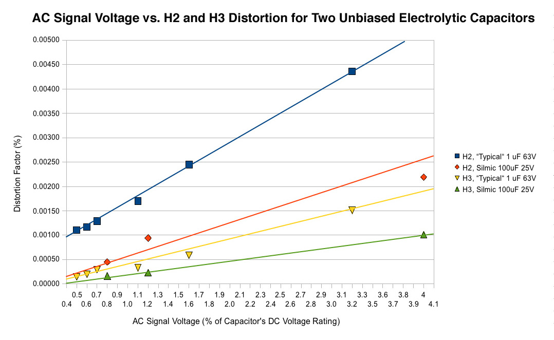
I used this Sengpiel Audio tool to convert the distortion attenuation measurements from Bateman's FFTs (in -dB) into distortion factor values (in %). I also expressed his AC voltages as % of cap rating, to make the comparison between different caps possible. I am very pleased that graphing in this way reveals a linear correlation between AC signal voltage and distortion. It shouldn't be too hard to just extend the trajectory of the best-fit lines for prediction purposes.
I am working on similar graphs for electrolytic distortion vs. DC bias voltage and hopefully another one for film caps.
This list now includes A) the effects of AC signal voltage on distortion and B) the concept of "optimum bias" (thanks to Cwtim01's comment). I condensed some other things a bit.
In the effort to make this information more accessible and useful for predicting capacitor distortion levels, I've also made some graphs to help illustrate these points. Here goes:
…………………………………………………………
CAPACITOR FACTS I LEARNED FROM CYRIL BATEMAN v2
1. Capacitor distortion does not correlate with dissipation factor or ESR, but rather with dielectric absorption. Bateman's tests suggest that dielectric absorption is in fact the main cause of capacitor distortion.
2. Capacitors have an "optimum bias" level. THD is higher below this level, and above it. According to Bateman, "Optimum bias for most conventional 25 volt polar electrolytics was between 1 volt and 4 volts DC, while for 50 - 63 volt rated capacitors, optimum bias ranged from less than 2 volts to some 7 volts DC" (Capacitor Sounds 5, pg. 10). Note that "optimum bias" indicates lowest possible THD without regard for harmonic profile.
3. A capacitor's H2 distortion (only) increases with DC bias voltage. An electrolytic cap biased at 50% of its voltage rating produces 6 times more THD than the same cap biased at just 10% of its rating, owing almost entirely to increased H2. For one electrolytic, a very low bias (below 10% of rating), minimized H2 to the point that H3 dominated the harmonic profile (yuck!). With bias at 20% of the voltage rating, H2 rose to equal H3, and and at all higher bias voltages beyond 20% of the rating, H2 dominated.
4. Both H2 and H3 distortions increase with AC signal voltage. Bateman warms: "[w]hen third harmonic distortion exceeds some 0.0003% of the test signal, intermodulation distortions become visible above the measurement noise floor. Any increase in AC signal results in much increased intermodulation and harmonic distortions" (Capacitor Sounds 5, pg. 11).
5. Bi-polar electrolytic caps distort half as much as their polar counterparts, and have less dielectric absorption too. Too bad they're big!
6. A film bypass with with an electrolytic cap can reduce distortion--larger bypasses more effectively so. A bypass with a capacitance of 10% of the main electrolytic proved marginally effective at reducing distortion, while a bypass with just 1% of the main cap's value yielded an insignificant reduction.
7. Film caps distort far less than electrolytics. A PET cap distorts 1/6 as much an optimally-biased polar electrolytic cap of the same capacitance, and 1/3 as much as a bi-polar electrolytic cap.
8. Polypropylene film caps distort less than polyesters. An unbiased WIMA MKS metallised PET cap distorted 2x as much as a WIMA FKP foil/PP cap and introduced significant IMD to the signal. When biased at 18v, the MKS distorted 28x as much as the FKP cap!
9. Foil/film caps distort less than metallised film caps. The #7 comparison isn't quite fair. Even polyester performs decently with a foil electrode. The WIMA FKS foil/PET series measured "almost as good" as WIMA FKP2 (Bateman's words in quotes, no direct comparisons were published). Hooray for foil.
10. COG ceramic disc caps distort thousands of times less than X7R ceramics. Bateman's XR7 cap test produced the scariest FFT I've ever seen! THD of .48%, 8000 times the distortion of the COG ceramic cap.
11. Other excellent dielectric options exist. Polycarbonate and polystyrene caps have very low distortion but are hard to find. Polyphenylene Sulphide caps are worth consideration: with a footprint only slightly larger than metallised PET, PPS caps distort almost as little as polypropylene caps.
......................................
So here is a graph that illustrates point #4 for electrolytic caps. (Pardon me...I flexed my primitive Excel skills to create this) There are some obvious gaps in Bateman's measurements, but certainly enough to establish a clear trend.
I used this Sengpiel Audio tool to convert the distortion attenuation measurements from Bateman's FFTs (in -dB) into distortion factor values (in %). I also expressed his AC voltages as % of cap rating, to make the comparison between different caps possible. I am very pleased that graphing in this way reveals a linear correlation between AC signal voltage and distortion. It shouldn't be too hard to just extend the trajectory of the best-fit lines for prediction purposes.
I am working on similar graphs for electrolytic distortion vs. DC bias voltage and hopefully another one for film caps.
Attachments
Last edited:
- Home
- Amplifiers
- Headphone Systems
- BF862 based SE Class A Headamp without the HEAT