Very nice work "X"!
Now you've got me drooling all over my keyboard posting photos of that Silicon Harmony amplifier.
Somebody...please get me some paper towels before I short out my keyboard.
I'm sure some folks would easily give up their left nut for that high-end SMPS powered headphone amplifier instead of paying almost $2k for it.
Keep up the good work, "X". I look forward to your future designs.
Amp porn
Yes, you're right.
Now...everybody please excuse me while I spank the 'ole monkey.
Sorry "X", but your designs and Prasi's layouts are going to get the best of me.

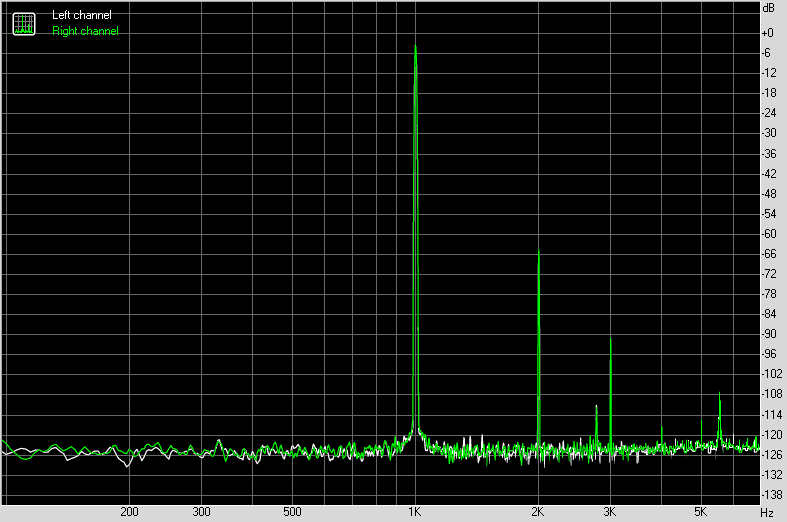
Those little peaks are an anomaly - perhaps the DC to DC switch mode step up converter is not working right. It was not there earlier - so I am investigating. I do hear an audible buzz in the converter (with my plain ears when near the amp) that wasn't there before. Sounds like 2.8kHz - you can't hear that as the level shown by the FFT is very low.
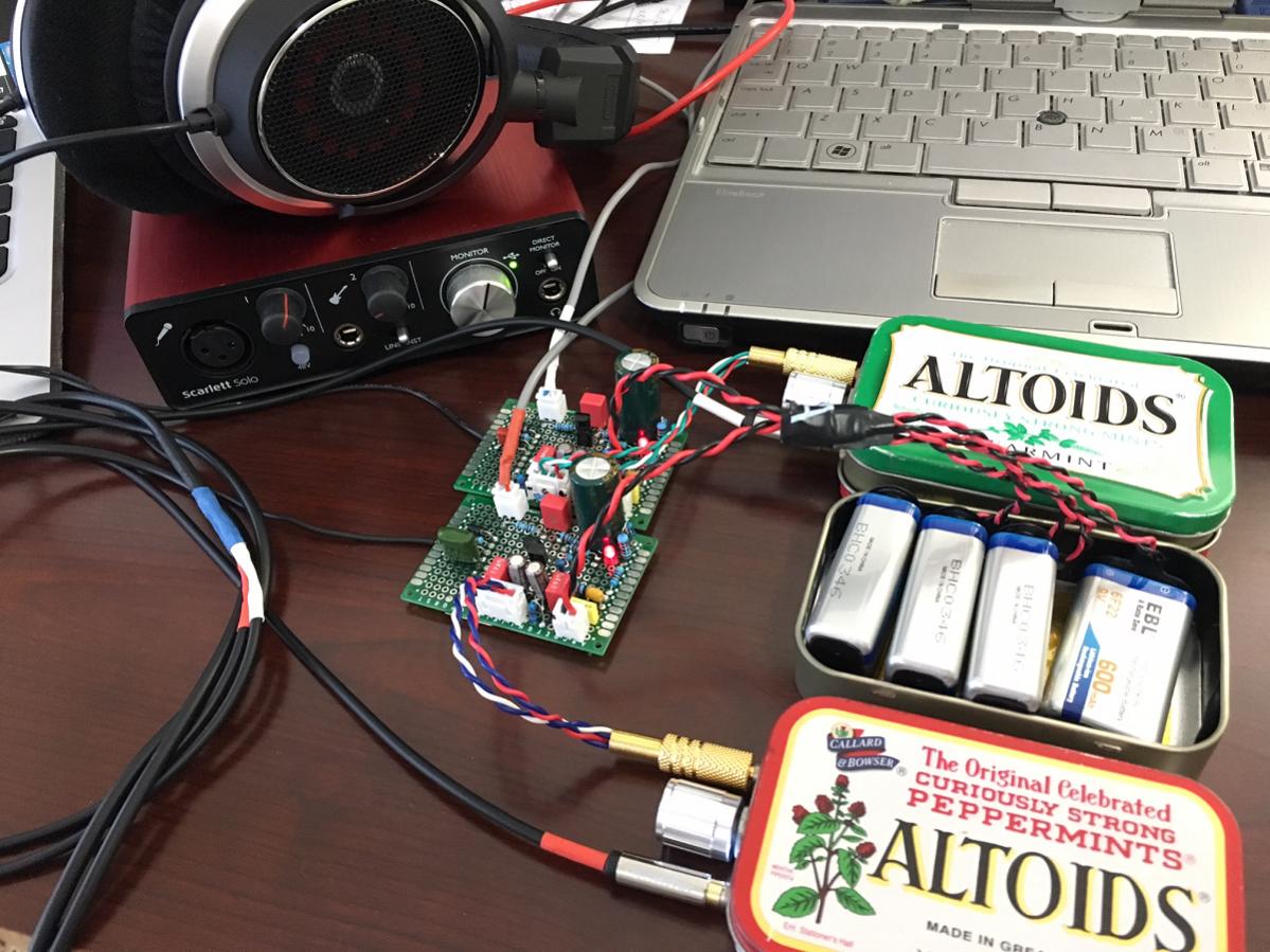
SE Class A balanced line driver for balanced headphones with two Pocket Amps.
http://www.diyaudio.com/forums/group-buys/302859-xrk971-pocket-class-headamp-gb-88.html#post5121677
http://www.diyaudio.com/forums/group-buys/302859-xrk971-pocket-class-headamp-gb-88.html#post5121677
In your as-built model, you changed R11a, R11b, R11c, and R11d from 1R to 33R. Was this a model-only change, or did you change this to reduce dissipation through the FETs? I've just started soldering parts on my board, and want to keep abreast of changes me by others and why. Why make the same mistake twice?
Hi, how did you find these boards/design?
Asking as I have recieved mine from oshpark.
I'll use cerafine or Silmic for output, I have both. I'll use cerafine for the 4u7(I have both there too, as well as MKS2's).
I'll use takman metal films for the majority of the resistors, but PRP 1W for the 20R.
I have some Vishay 0.1% I'll use for 470R and some Dale and PRP 0.25W to choose from for the 100K.
As to what caps and resistors to use where, I think that's a matter of taste as long as the quality is decent.
I'll use takman metal films for the majority of the resistors, but PRP 1W for the 20R.
I have some Vishay 0.1% I'll use for 470R and some Dale and PRP 0.25W to choose from for the 100K.
As to what caps and resistors to use where, I think that's a matter of taste as long as the quality is decent.
Hi, how did you find these boards/design?
Asking as I have recieved mine from oshpark.
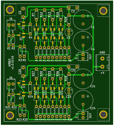
Are we talking about this layout (from post 75)?
How closely matched does the BF862's need to be?
I've got 100pcs on the same strip, the first 15 or so I've tested are mostly 13-15mA Idss, mainly 13.5-14.2mA.
I'm thinking getting 0.1% or so may be difficult with the 100pcs I have.
I managed to get 20pcs with Idss 13.4mA - 13.8mA out of the 100pcs I have. That is the closest I can get for that many. The good thing about this tedious process is that I now have some quads and pairs with very close matches for Idss.
That sounds pretty good match what you describe. 13.4mA to 13.8mA.
I would have prefered something closer to 1%, but not enough to go get another strip of 100 BF862's.
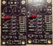
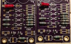
The boards are slowly populating as I can only do so much before the pain in my back gets too overwhelming.
Resistors are Takman metalfilm and PRP metalfilm.
Attachments
Looking good. This amp has a nice sound and being a single ended push pull, is a great topology. Having to match the FETs though, leads me to just use a bigger MOSFET like an IRF610 driven by a BF862.
Thanks
Having matched the jfet's and getting closer and closer to testing the headamp, I'm sticking with this.
It'll be interesting to compare it to my version of the ad797/buf634 headamp with TPS7A4700/3301 regs as well as to my BCL clone with cherry-picked parts.
Only thing above this headamp I have yet to decide is PS.
It is a single ended supply so very simple. I like to use DC step up modules and CRCRC filters so even a 5v portable battery pack can be used. On mine, I added a cap multiplier to give it a ramp up soft start. Certainly linear trafo and CRC followed by a nice LT LDO linear voltage regulator can work as well.
I used CLC filtering after the TPS7A4700/3301 on my version of the AD797/BUF634 version.
I do have a 18Vdc 1-2A wallwart, I could use that followed by some capacitance and filtering.
0-9Vac 1500mA transformer I have a few of, followed by a voltage doubler and then some filtering.
I know the VA of those transformers above what's needed, but that's what I have. I think I have some Panasonic HA 22000uF/25V caps as wełl, not sure how happy an smps wallwart would be about one or two of those though.
- Home
- Amplifiers
- Headphone Systems
- BF862 based SE Class A Headamp without the HEAT