I see?
If Vp = 180V and Ip = 11mA, then rp = 6k ohms.
If Vp = 180V and Ip = 20mA, then rp = 8k ohms.
@rongon I'm learning a lot how to calculate the OPT value, really appreciate your help.
You're looking at the wrong curves on the graph. I think you are looking at the mu curves.
Plate resistance at 20mA is around 2K, and 11mA around 3.5K
Seems like a 5842 would be a much better match in this application and similar operating points of say 15mA or so.
Yeah, but... Compromises everywhere.
How low of a bias voltage is acceptable for a 5842 used this way? Is a grid bias of -1.2V going to result in too much grid current?
Looking at https://frank.pocnet.net/sheets/185/5/5842.pdf :
Normally I'd use a red LED and accept the resulting grid bias of -1.8V. For 5842 at Ip = 15mA and Vg = -1.8V, that would mean Vp = 145V. At those points, rp will be about 2k ohms. No improvement in frequency response over a 5687 run with Ip = 20mA.
However, if we run that 5842 really hot, let's say Vp = 135 and Vg = -1.2V and Ip = 24mA, now rp will be down around 1.7k ohms. That would make the fc about 27Hz. That's an improvement, but would that be a night and day difference from a 5687 with Ip = 22mA or so?
If you try to use a triode with mu = 8, into that OPT with a 5:1 turns ratio, with 1V rms input, 5V rms out from the tube's plate, stepped down by 5, we get unity gain. Maybe a little less gain than that due to the inevitable losses.
So we want a triode with:
mu = >15
rp = <1k
Ip = <40mA
I suggest paralleled 5687; one 5687 twin-triode per channel.
5687 paralleled:
mu = 15 (or thereabouts)
rp = 1k
Ip = 40mA
With that 10H primary, fc should be about 16Hz. Not ideal, but good enough.
Yup, that's what I would do.
--
Last edited:
Hey Merlin, could you send me some measurements from your Edcor GXSE5-15K transformer?
Primary Inductance (in henries) - measure from Pin 1 to Pin 5
Primary DC resistance (in ohms) - measure from Pin 1 to Pin 5
Secondary inductance (in henries) - measure from Pin 7 to Pin 9
Secondary DC resistance (in ohms) - measure from Pin 7 to Pin 9

With that information, I can make a spice model, to make some very approximate simulations.
Yes, that's basically it.
You'll want an input DC blocking capacitor, of course. You will also need a grid leak resistor. A grid stopper resistor will likely be needed too (the 5687 has high gm, especially two of them paralleled).
--
Primary Inductance (in henries) - measure from Pin 1 to Pin 5
Primary DC resistance (in ohms) - measure from Pin 1 to Pin 5
Secondary inductance (in henries) - measure from Pin 7 to Pin 9
Secondary DC resistance (in ohms) - measure from Pin 7 to Pin 9
With that information, I can make a spice model, to make some very approximate simulations.
@rongon
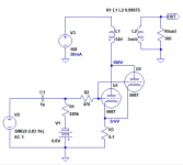
As attached schematic?
Yes, that's basically it.
You'll want an input DC blocking capacitor, of course. You will also need a grid leak resistor. A grid stopper resistor will likely be needed too (the 5687 has high gm, especially two of them paralleled).
--

6AS7G (6N5P) as an input tube (totem-pole config) to drive a 5687 (6N6P) cathode follower with active load? Am i understanding that correctly?
--
On further reflection, I think I'm underestimating the insertion loss of the output transformer. How much gain will be lost across a little 5W SE transformer like that Edcor GXSE5-15K-600? 1dB 2dB? More?
--
Hey Merlin, could you send me some measurements from your Edcor GXSE5-15K transformer?
Primary Inductance (in henries) - measure from Pin 1 to Pin 5
12H
Primary DC resistance (in ohms) - measure from Pin 1 to Pin 5
263 ohms
Secondary inductance (in henries) - measure from Pin 7 to Pin 9
0.38H
Secondary DC resistance (in ohms) - measure from Pin 7 to Pin 9
24 ohms
View attachment 689017
With that information, I can make a spice model, to make some very approximate simulations.
Yes, that's basically it.
You'll want an input DC blocking capacitor 0.47uF?, of course. You will also need a grid leak resistor100K?. A grid stopper resistor 1K?will likely be needed too (the 5687 has high gm, especially two of them paralleled).
--
Why the inductance is high from the measurement of yesterday? Can be today still not powered?
Last edited:
No, the 6N5P is a small signal tube. 6N5P tube. Audiophile double triode ― Hi-End vacuum tubes, sockets, capacitors, nixie. Retail and wholesale to worldwide.View attachment 689019
6AS7G (6N5P) as an input tube (totem-pole config) to drive a 5687 (6N6P) cathode follower with active load? Am i understanding that correctly?
--
You can sub 6N1P...
View attachment 689019
6AS7G (6N5P) as an input tube (totem-pole config) to drive a 5687 (6N6P) cathode follower with active load? Am i understanding that correctly?
--
On further reflection, I think I'm underestimating the insertion loss of the output transformer. How much gain will be lost across a little 5W SE transformer like that Edcor GXSE5-15K-600? 1dB 2dB? More?
--
Why the inductance is high from the measurement of yesterday? Can be today still not powered?
@rongon
Have you done the simulation?
Oops... I forgot!  I'm making a note to myself; will try to do that this evening.
Question:
Is the DC resistance of the secondary really 24 ohms? That seems awfully high. Can you double-check that?
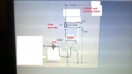
Also, your biasing scheme isn't complete. I can fill in parts to make it work. Do you really have to have -6.6V bias on the 5687 grids?
I'm making a note to myself; will try to do that this evening.Question:
Is the DC resistance of the secondary really 24 ohms? That seems awfully high. Can you double-check that?
Also, your biasing scheme isn't complete. I can fill in parts to make it work. Do you really have to have -6.6V bias on the 5687 grids?
Last edited:
You'll want an input DC blocking capacitor 0.47uF?, of course. You will also need a grid leak resistor100K?. A grid stopper resistor 1K?will likely be needed too (the 5687 has high gm, especially two of them paralleled).
All the above are sensible values.
The grid stopper could probably be as low in value as 100R. 470R would work. The value isn't critical, but it should be enough to inhibit a high gm tube's tendency to oscillate. Too high a value and you risk some treble roll-off from interaction with the triode's Miller capacitance.
More here: The Valve Wizard
--
Oops... I forgot!
Question:
Is the DC resistance of the secondary really 24 ohms? That seems awfully high. Can you double-check that?
Yes 24 ohms double-checked
Also, your biasing scheme isn't complete. I can fill in parts to make it work. Do you really have to have -6.6V bias on the 5687 grids?
I want to try two bias: -3.3V grid 100V plate 14-15mA and -6.6V grid 150V plate 14-15mA
Last edited:
Oops... I forgot!
Also forgot the most important thing of OPT simulation: the coupling coefficient.
K: 1-(Lsp/Lp)
Lp: primary inductance
Lsp: leakage inductance. Measured primary inductance when secondary is shorted.
for example:
Lp: 20H
Lsp: 3mH
K: 0.99985
LTspice Spice directive: K L1 L2 0.99985
OK, quick 'n dirty simulation.
First, I'm not sure whether the OPT primary inductance is really 12H or 20H. I picked 12H, to be conservative.
Second, I changed the coupling coefficient to fit that. It's 0.99975 instead of 0.99985, because of the 12H primary L.
Bandwidth looks good. Too good on the high frequency end. I don't trust it.
As far as gain and power output, what I get is not encouraging. I think something's wrong with the OPT measurements, because there's a really large insertion loss. The total gain of the proposed amp is only 0.25X or -15dB (that's negative gain).
It takes 2.83V peak input to reach 710mV peak output, at 0.88% THD. The FFT display shows that the amp is nearly clipping at that level.
Changing Rload to 600 ohms doesn't help much at all. THD still 0.88% and gain is only very slightly higher.
I've attached the .asc file in case anybody wants to have a look.
Attachments
Last edited:
- Status
- This old topic is closed. If you want to reopen this topic, contact a moderator using the "Report Post" button.
- Home
- Amplifiers
- Headphone Systems
- 5687 headphone amp