Where did I say, or even imply, that my design are better than "the rest of you"?
You asked for a suggestion for an ebay kit, and I told you I am sorry, but I prefer not to buy ebay kits, and hence have no experience to suggest one.
There are countless schematics on this site, with people sometimes offering PCBs.
If not, you can have PCBs made for cheap (using the posted Gerber files), and head to Digikey or Mouser to pick the various components.
Clearly, it is going to be more expensive than an ebay kit.
But if you consider the probability of getting a lemon by buying ebay kits, and you include that into the cost, that "more expensive" might suddenly look not so expensive after all.
I started this thread for a specific Ebay kit, the E19 headphone amp. It is to share information on how well it works and how to make it better.
Layout of double sided PCB is beyond the skill of me, and most other forum members. It is not for everyone. The E19 is meant for a fun weekend project.
If this type of project is below your level, please, start your own thread.
Last edited:
Several different amps have been mentioned here.
Is the E5 as good or better than the E19?
The E5 is a good board of known quality. The E19 is a reject which has design defect and needs Nattawa's fix to make it work. No comparison.
The "Reference HA5000 amp" has more drive current capability on paper and may work better with low impedance phones. But the quality is unknown. If it works as advertised, it should be a more dynamic amp. Wish someone who had used the HA5000 clone will post.Is the more expensive "Reference HA5000 amp" suppose to be better than the E5 and E19?
Last edited:
The E5 is a good board of known quality. The E19 is a reject which has design defect and needs Nattawa's fix to make it work. No comparison.
Let me rephrase my question since I wasn't clear.
I'm wondering if the E19's sound quality is better than the E5's and if the HA5000 clone's is better than both of the E models?
I understand that the E19's board is crap and the E5 works right out of the box.
Let me rephrase my question since I wasn't clear.
I'm wondering if the E19's sound quality is better than the E5's and if the HA5000 clone's is better than both of the E models?
I understand that the E19's board is crap and the E5 works right out of the box.
I will be very interested in the answer to your question too.
The E5 is best documented among the 3 by its creator, Weiliang, on this forum:
http://www.diyaudio.com/forums/headphone-systems/221480-my-e5-class-hifi-headphone-amp.html
The E19 uses the same topology which may make it sound similar, but the devil is in the details. Nattawa built both and may have some insight.
The Audio Technica HA5000 is a $1200, very highend box. The clones may not follow it to the letters. You can find a discussion of the HA5000 at the RJM Blog on this forum. On paper, it is a better design than the E5/E19 using similar topology.
http://www.diyaudio.com/forums/blogs/rjm/1248-ha5000.html
I hope you did not get the same E19 that I ordered at ebay. <snip>
I put a 470uF/25V cap and the hum does not go away. It is very low level, but very bothersome. I may have solder the cap in such a way that there is still a ground loop. Back to the drawing board.
Otherwise, the E19 amp sound very, very good.
It probably matters where you solder the capacitor GND terminal. I soldered it right to the center pin of the AC input connector. If you have a smaller power rating transformer it may help, for its higher winding resistance helps reduce the peak charge current on the main caps. you could also insert a 1-ohm/1W resistor in each of the 12VAC inputs to help reduce the peak charge current.
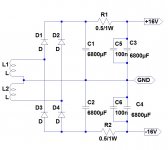
If the above does not suffice, it may take cutting up the traces and cleaning up the way the rectifier-smoothing cap current loops to establish a quiet common "Ground" that the amplifiers reference to. The attached picture is the C-R-C filter I now have with my E19, it was hard wired, and solder joints are made exactly where and only where the tie dots are.
To do this mod all four big caps have to be removed for you to get access to the traces on the component side. Be very patient as the caps have rigid snap-in type leads that are tightly fitted in the holes, and the pads can be easily damaged. Best to clamp the board on a vise, have a helper ready to pull the cap on your command while you're heating the pins with two soldering irons. If you damage the pads, it's not a big deal as you're hard-wiring them anyways. I damaged pads for one of the caps because I pulled it sooner than joints got hot enough. It's a double-sided board, you want to be sure the far side of a pad gets hot enough too.
Attachments
It probably matters where you solder the capacitor GND terminal. I soldered it right to the center pin of the AC input connector. If you have a smaller power rating transformer it may help, for its higher winding resistance helps reduce the peak charge current on the main caps. you could also insert a 1-ohm/1W resistor in each of the 12VAC inputs to help reduce the peak charge current.
If the above does not suffice, it may take cutting up the traces and cleaning up the way the rectifier-smoothing cap current loops to establish a quiet common "Ground" that the amplifiers reference to. The attached picture is the C-R-C filter I now have with my E19, it was hard wired, and solder joints are made exactly where and only where the tie dots are.
To do this mod all four big caps have to be removed for you to get access to the traces on the component side. Be very patient as the caps have rigid snap-in type leads that are tightly fitted in the holes, and the pads can be easily damaged. Best to clamp the board on a vise, have a helper ready to pull the cap on your command while you're heating the pins with two soldering irons. If you damage the pads, it's not a big deal as you're hard-wiring them anyways. I damaged pads for one of the caps because I pulled it sooner than joints got hot enough. It's a double-sided board, you want to be sure the far side of a pad gets hot enough too.
Many thanks again, Nattawa. This project turns out to be more challenging and fun than I first expect. I would not have been able to figure out the source of the problem and solution without your help. I will try repositioning the filter cap tonight using your suggestions. I use a small 30VA toroidal transformer.
I just received the Alps RK16 pot and will replace the RK09 too. I hope to finish it before Friday. Precision drilling the holes on the front panel will be challenging.
I put snubber circuits on each supply, where the power enters the board, was an improvement overall. This doesn't probably have any effect on humming/ground problems however.
Another great tip I rceived from a most well qualified source, was to place a 22pf silver mica cap across the the gate to rail of the outputs.
Another great tip I rceived from a most well qualified source, was to place a 22pf silver mica cap across the the gate to rail of the outputs.
Solder the cap right next to the transformer ground. The hum is still there, much lower, but still there.
I used an old cap from my tool box. Not sure how good it is and it may have too much leakage. I will try a fresh cap before messing with the ground traces.
Then, perhaps it does take re-wiring the power supply section to get rid of the hum.
An alternative to having to hack the board could be to build an out-board split rail DC PSU, like the one in the schematic in my last post, to supply the E19 instead of supplying it with the power transformer. Remove the 6,800uF caps and re-use them in the out-board DC PSU, do not leave them on the E19 board.
I don't think the quality of the 470uF cap would be a concern here, by the way.
I will try hacking the grounding loop using your picture in post #10 as the cut and patch guide. Anything that I should watch out for doing that?
I will try hacking the grounding loop using your picture in post #10 as the cut and patch guide. Anything that I should watch out for doing that?
I'm afraid those pictures may not be sufficient to serve as a good guide. Unfortunately I did not document every step of what I did.
There are trace cuts on both sides of the board, most of them are on GND wires, a few on +V and -V for inserting the 0.5-ohm resistors to form the C-R-C filter. I drilled a few holes to fit the resistors. The size of space on the board is plenty for this mod, you can improvise your own scheme. The bottom line is you do not want any part of the amplifier to tap into the GND node of the power supply at more than one physical spot. I'll try to take a few more pictures this weekend and see if that will make things a bit more clear.
I have some "LM317 LM337" based DC power supply boards in my tool box. The cap on each rail is much smaller, 1000uF/35V, but it is IC regulated. What do you think of using it?
I have some "LM317 LM337" based DC power supply boards in my tool box. The cap on each rail is much smaller, 1000uF/35V, but it is IC regulated. What do you think of using it?
That will beat the on-board un-regulated PSU hands down, and a very clean, mess-free mod too.
You will need to wire the positive output from the rectifier at the input of the 317 to the input of the 7812 on the E19 board, and remove the 470uF cap you put in.
Build log of E19 headphone amplifier
I have a completely assembled E19 headphone amplifier in an aluminum enclosure. The sound is excellent in staging and dynamics, but a low level hum persists. The hum is most noticeable with Sennheiser HD598. With the Sennheiser PXC250 or the very old HD-420, the hum is hardly noticeable. My next phase is to add a fully regulated power supply.
Below is a pictorial building log of the E19 project:
The board
E19 headphone amplifier build log
I have a completely assembled E19 headphone amplifier in an aluminum enclosure. The sound is excellent in staging and dynamics, but a low level hum persists. The hum is most noticeable with Sennheiser HD598. With the Sennheiser PXC250 or the very old HD-420, the hum is hardly noticeable. My next phase is to add a fully regulated power supply.
Below is a pictorial building log of the E19 project:
The board looks very good build quality, but has design fault as nattawa pointed out in his post #2.
The location of the volume control and headphone jack are different from any pre-drilled enclosure for headphone amplifier. I got a blank panel enclosure. The picture shows the bottom with masking tap for marking the drill location for mounting. I use leftover mounting post from my computer building day. It works very well. It is very difficult to drill the precision location on the front and back panel with a small table top drill press, not recommended. The transformer is a 30VA toroidal. Total parts outlay is just under $100 at this point.


I drill ventilation holes on the side and top panels.


The E19 board uses a small RK9 style volume pot which makes the volume knob sits very low. I replaced it with an Alps RK16, 50K pot. It sells for $7 on Ebay.


The finished headphone looks fine. I added a filter capacitor to the 7812 regulator for the protection circuit. It reduced the hum, but did not completely eliminate it.


I have a completely assembled E19 headphone amplifier in an aluminum enclosure. The sound is excellent in staging and dynamics, but a low level hum persists. The hum is most noticeable with Sennheiser HD598. With the Sennheiser PXC250 or the very old HD-420, the hum is hardly noticeable. My next phase is to add a fully regulated power supply.
Below is a pictorial building log of the E19 project:
The board looks very good build quality, but has design fault as nattawa pointed out in his post #2.
The location of the volume control and headphone jack are different from any pre-drilled enclosure for headphone amplifier. I got a blank panel enclosure. The picture shows the bottom with masking tap for marking the drill location for mounting. I use leftover mounting post from my computer building day. It works very well. It is very difficult to drill the precision location on the front and back panel with a small table top drill press, not recommended. The transformer is a 30VA toroidal. Total parts outlay is just under $100 at this point.
I drill ventilation holes on the side and top panels.
The E19 board uses a small RK9 style volume pot which makes the volume knob sits very low. I replaced it with an Alps RK16, 50K pot. It sells for $7 on Ebay.
The finished headphone looks fine. I added a filter capacitor to the 7812 regulator for the protection circuit. It reduced the hum, but did not completely eliminate it.
Last edited:
I'm sure that hum is very frustrating after all the work you've done.
Too bad the board wasn't designed correctly to begin with.
Yes, I am disappointed, but NOT exactly surprised. It is the nature of getting China-designed-made electronics on Ebay. There were very high quality gems mixed among junks. I tried to identify reliable sellers and come to forum like this to get information. A few years ago, it will not be possible to assemble this professional looking headphone amp at the cost I paid. Most importantly, the amp does sound very good driving the HD598.
I could have purchased the E-5 head amp board and pre-drilled enclosure at the same total cost. I felt like being more adventurous when I bought the E19. With more effort and additional parts, I believe I can get a hum free, high quality head amp box. Wish me luck in my adventure.
The hum is barely noticeable with Sennheiser HD598, but I am very sensible to hum. With the Sennheiser PXC250 or the very old HD-420, the hum is hardly audible. As is, the E19 head amp with the filter cap for the protection circuit may be acceptable to 90% of the users. It is a fun project to add the regulated supply.
Last edited:
- Status
- This old topic is closed. If you want to reopen this topic, contact a moderator using the "Report Post" button.
- Home
- Amplifiers
- Headphone Systems
- E19 headphone amplifier board K2381 J407 MOSFET Yuanjing Audio