Anything wrong with my using a Switchcraft 14B with five connections/pins as my input jack along with a 1/8" Female to 1/4" Male adapter? I need a beefier and longer chassis/panel jack for my case.
That's kind of pricey. Similar Neutrik for less. These have the ground connected to chassis ground, which in some cases, may cause hum. You are better off with isolated jacks in general.
In USA:
Neutrik Rean NYS230 1/4" Stereo Jack Non-Switched
Aliexpress (not name brand):
1/4inch 6.35mm stereo TRS with switch socket jack female connector panel mount Solder-in Connectors from Lights & Lighting on Aliexpress.com | Alibaba Group
I really like these locking isolated ones:
1pc Professional speaker plug Audio Jack 6.35mm female socket panel mount xlr connector black&silver colors banana plugs rca-in Connectors from Lights & Lighting on Aliexpress.com | Alibaba Group
Understood, great advice for the headphone output jack but don't I require a switching two-position 5-pin/connection input jack for the audio source?That's kind of pricey. Similar Neutrik for less. These have the ground connected to chassis ground, which in some cases, may cause hum. You are better off with isolated jacks in general.
In USA:
Neutrik Rean NYS230 1/4" Stereo Jack Non-Switched
Aliexpress (not name brand):
1/4inch 6.35mm stereo TRS with switch socket jack female connector panel mount Solder-in Connectors from Lights & Lighting on Aliexpress.com | Alibaba Group
I really like these locking isolated ones:
1pc Professional speaker plug Audio Jack 6.35mm female socket panel mount xlr connector black&silver colors banana plugs rca-in Connectors from Lights & Lighting on Aliexpress.com | Alibaba Group
Good sir, with absolutely no disrespect intended (not intending to be argumentative nor challenging in any way, shape, or form) why would agdr use/require/recommend a switching jack for his audio input in the first place?Any 3.5mm TRS works - I use the nice switchcraft ones that AGDR specs on his amp for in and out because they are well built and reliable but I don’t think switching is a necessity.
Post #274
...The voltages and currents coming out of the Super CMOY are so low just about any 3.5mm or1/4" jack you find will meet specifications. As for the number of contacts, look at the symbols in my schematic for the Super CMOY and match them up with your jack. The input jack needs 2 contacts with two switches, so 5 connections total coming out of the jack (including ground). The output jack doesn't use the switches, so just the 3 connection type works (or the 5 with the switch contacts ignored, which is what the schematic shows)...
How would one correctly wire-up a 3-contact or 4-contact TRS jack (like the ones you so kindly recommended and linked in Post #302) to the PCB? I carefully mulled over agdr's schematic and I do believe I see what you mean about any jack can be used but still remain uncertain...

I also reread the following post from agdr in which he mentions the use of non-switching RCA input jacks which only provide a pair of contacts each for a total of only four contacts/connections.
Post #156
Here is the companion diagram on how to wire up external RCA jacks for the input. The third hole in the middle towards the back of the input jack isn't used here, that is just another ground.
Keep in mind that with RCA jacks they won't automatically ground with nothing plugged in, so you might hear some hiss if turned all the way up with the inputs unconnected (as with any amp). The equivalent thing to use if you want to check background noise with the inputs grounded is RCA shorting plugs on both inputs.
Last edited:
Gotcha, I understand now. Do you happen to have a recommendation for where to ground the shielding in a wooden case? Or no need to ground in this situation.They “switch” to GND when jack is unplugged but that is of no consequence as input already is tied to GND via 47k resistor and 10k pot. The switching jack provides 5 solder kind for extra strong mechanical durability when plugging and unplugging jack.
Wooden case cannot be a shield. Are you adding internal metal shield box? If there is a shield box, it’s only effective if there are no gaps larger than about 2mm. Ground it earth mains ground if you are running AC supply to your box. If not ground to circuit GND (0v). If running mains into your box, your analog ground of the amp should be isolated from earth ground with a ground loop breaker (GLB) consisting of two antiparallel 1N400X diodes, paralleled with 1W 10ohm resistor and paralleled with 0.1uF film cap. One end goes to analog 0v GND. Other end goes to earth mains/shield ground. This helps to reduce hum and noise from ground loops with your other equipment. Be careful of metal cases and inadvertent ground connections to non insulated panel jacks like RCA or 3.5mm jacks etc.
I was planning to cover the entire inside of a wooden case with copper foil tape with conductive adhesive... similar to what is done with electric guitars. Just wondering where a grounding wire from the copper would go... A heat sink perhaps or the ground on the headphone jack?Wooden case cannot be a shield. Are you adding internal metal shield box? If there is a shield box, it’s only effective if there are no gaps larger than about 2mm. Ground it earth mains ground if you are running AC supply to your box. If not ground to circuit GND (0v). If running mains into your box, your analog ground of the amp should be isolated from earth ground with a ground loop breaker (GLB) consisting of two antiparallel 1N400X diodes, paralleled with 1W 10ohm resistor and paralleled with 0.1uF film cap. One end goes to analog 0v GND. Other end goes to earth mains/shield ground. This helps to reduce hum and noise from ground loops with your other equipment. Be careful of metal cases and inadvertent ground connections to non insulated panel jacks like RCA or 3.5mm jacks etc.
Last edited:
The extra 2 holes on the board under the output jack are not used. Those are switches which *are* used in the input jack to ground the contacts. Just to simpify the BOM (and prevent part mix-ups!) I used the same jack for output as for input.
agdr linked photo
agdr linked photo
Just would like the clarify the above. Are those switches really necessary for an external input jack? Would implementing a non-switched three-contact isolated input jack create a problem?
Hi guys! Sorry, hit a busy patch again.
Speed Hunter - PM (just now) sent.")
xrk971 - I haven't had any luck here (Texas) with sending PC boards in a standard envelope. The postal clerks always note (I've tried it several times) they are "unbendable", which is postal parlance means "not machinable". The Post Office can't run them through letter sorting machines at the sorting centers, have to be sorted by hand. So they have to go "international small parcel" which is $14. Hey any tricks you have here, please share!! $14 is ridiculous to send a tiny PC board. I wish the USPS had a "small package" rate, like Canadian Post does, something half the cost of $14.
WoodyLuvr - you do need the switch contacts on the input jack. Don't use a 3 contact jack, you need all 5 - 3 contact and two switches. The switches are there to ground the inputs to the amplifier when nothing is plugged in, so you don't get hiss and noise. It is a bigger deal than one would think in actual usage, especially with the volume turned up and nothing plugged in - you won't hear anything this way. Otherwise you will hear hiss from input noise pickup. NwAvGuy's O2 Headphone amplifier does the exact same thing (jack with grounded switch contacts) and it works wonderfully, which is why I designed it this way on the Super CMOY.
So you need a panel mounted jack with the two switch contacts in there. You only need to run 3 wires to the panel jack though (be sure to twist all 3 together):
* The PCB hole labelled T or "left" is one of the jack contacts. Google "TRS Jack" for the wikipedia page, then scroll down. One of the pictures on the right edge shows which part is left and right. The tip of the plug is left, the ring is right, and the bottom part is the shield. You just need to figure out which contact on your jack mates up with the tip on the plug and that is your Left. You can do this via the diagram in the jack data sheet, or the old fashioned way of just taking an ohm meter, sticking the probe into the jack to contact the "tip" contact, and then measure the jack connection contacts to find which one that is.
* The PCB hole labelled R or "right" is the other jack contact. So figure out which jack contact mates with the ring on the plug and that is right.
* And finally the S on PCB is the ground (as are the other two holes down the middle, which are the switch contacts, but you don't need to run any wires to those). So you just need one more wire going from S on the board to 3 places on your jack: the contact that mates with the shield part on the jack (bottom part), and then to both switch contacts on the jack.
Speed Hunter - PM (just now) sent.
xrk971 - I haven't had any luck here (Texas) with sending PC boards in a standard envelope. The postal clerks always note (I've tried it several times) they are "unbendable", which is postal parlance means "not machinable". The Post Office can't run them through letter sorting machines at the sorting centers, have to be sorted by hand. So they have to go "international small parcel" which is $14. Hey any tricks you have here, please share!! $14 is ridiculous to send a tiny PC board. I wish the USPS had a "small package" rate, like Canadian Post does, something half the cost of $14.
WoodyLuvr - you do need the switch contacts on the input jack. Don't use a 3 contact jack, you need all 5 - 3 contact and two switches. The switches are there to ground the inputs to the amplifier when nothing is plugged in, so you don't get hiss and noise. It is a bigger deal than one would think in actual usage, especially with the volume turned up and nothing plugged in - you won't hear anything this way. Otherwise you will hear hiss from input noise pickup. NwAvGuy's O2 Headphone amplifier does the exact same thing (jack with grounded switch contacts) and it works wonderfully, which is why I designed it this way on the Super CMOY.
So you need a panel mounted jack with the two switch contacts in there. You only need to run 3 wires to the panel jack though (be sure to twist all 3 together):
* The PCB hole labelled T or "left" is one of the jack contacts. Google "TRS Jack" for the wikipedia page, then scroll down. One of the pictures on the right edge shows which part is left and right. The tip of the plug is left, the ring is right, and the bottom part is the shield. You just need to figure out which contact on your jack mates up with the tip on the plug and that is your Left. You can do this via the diagram in the jack data sheet, or the old fashioned way of just taking an ohm meter, sticking the probe into the jack to contact the "tip" contact, and then measure the jack connection contacts to find which one that is.
* The PCB hole labelled R or "right" is the other jack contact. So figure out which jack contact mates with the ring on the plug and that is right.
* And finally the S on PCB is the ground (as are the other two holes down the middle, which are the switch contacts, but you don't need to run any wires to those). So you just need one more wire going from S on the board to 3 places on your jack: the contact that mates with the shield part on the jack (bottom part), and then to both switch contacts on the jack.
Last edited:
Well understood. Thank you for clarifying good man.Hi guys! Sorry, hit a busy patch again.
Speed Hunter - PM (just now) sent.
WoodyLuvr - you do need the switch contacts on the input jack. Don't use a 3 contact jack, you need all 5 - 3 contact and two switches. The switches are there to ground the inputs to the amplifier when nothing is plugged in, so you don't get hiss and noise. It is a bigger deal than one would think in actual usage, especially with the volume turned up and nothing plugged in - you won't hear anything this way. Otherwise you will hear hiss from input noise pickup. NwAvGuy's O2 Headphone amplifier does the exact same thing (jack with grounded switch contacts) and it works wonderfully, which is why I designed it this way on the Super CMOY.
So you need an panel mounted jack with the two switch contacts in there. You only need to run 3 wires to the panel jack though:
* The PCB hole labelled T or "left" is one of the jack contacts. Google "TRS Jack" for the wikipedia page, then scroll down. One of the pictures on the right edge shows which part is left and right. The tip of the plug is left, the ring is right, and the bottom part is the shield. You just need to figure out which contact on your jack mates up with the tip on the plug and that is your Left. You can do this via the diagram in the jack data sheet, or the old fashioned way of just taking an ohm meter, sticking the probe into the jack to contact the "tip" contact, and then measure the jack connection contacts to find which one that is.
* The PCB hole labelled R or "right" is the other jack contact. So figure out which jack contact mates with the ring on the plug and that is right.
* And finally the S on PCB is the ground (as are the other two holes down the middle, which are the switch contacts, but you don't need to run any wires to those). So you just need one more wire going from S on the board to 3 places on your jack: the contact that mates with the shield part on the jack (bottom part), and then to both switch contacts on the jack.
The OPA1688 Parallel Super Cmoy amp that I received from (and built by) @adydula sounds amazing! Dead quiet and the bass (sub bass) is monstrous. Very pleased to say the least.
Have you yet received and tested the Adafruit Switching Split Power Supply (±12V 500mA) AC-DC Wall Wart? Very curious to hear your thoughts about it.
BTW: In regards to the RECOM POWER RW-0509D ISOLATED DC-DC CONVERTER 4.5V to 9V via USB 2.0 CABLE SET-UP DIAGRAM I am planning to use the following cable, which is a less expensive two-wire power supply variant:
5V USB 2.0 Male Jack 2 Pin 2 Wire Power Charge Cable Cord Connector DIY 1m Wire
Last edited:
The RECOM DC-DC Converter arrived along with the 499R resistors and heat sink.
Think I will be able to bend over pins 2 & 3 and 22 & 23 and solder them together with no issues then solder the usb power cable leads to each as according to my diagram at the bottom of this post.
The resistors between pins 9 & 11 and 14 & 16 will need to be stood off to the sides as follows so as to provide enough pin area to solder on the four (4) power leads to the PCB.
An externally hosted image should be here but it was not working when we last tested it.
An externally hosted image should be here but it was not working when we last tested it.
An externally hosted image should be here but it was not working when we last tested it.
An externally hosted image should be here but it was not working when we last tested it.
Have you yet received and tested the Adafruit Switching Split Power Supply (±12V 500mA) AC-DC Wall Wart? Very curious to hear your thoughts about it.
BTW: In regards to the RECOM POWER RW-0509D ISOLATED DC-DC CONVERTER 4.5V to 9V via USB 2.0 CABLE SET-UP DIAGRAM I am planning to use the following cable, which is a less expensive two-wire power supply variant:
5V USB 2.0 Male Jack 2 Pin 2 Wire Power Charge Cable Cord Connector DIY 1m Wire
I did some tests on the Split power supply today! I received 3 of them a couple of weeks ago. I'll post scope shots tonight, but the summary is that it seems OK.
The switching frequency appears to be around 67KHz, with a 100mV peak spike. Above the audio frequency range. Well, sort of.
Feed in square waves to an audio amp and the Fourier series can go out to 100KHz to get nice sharp corners on the wave. For that reason some folks build audio amps with a 100Khz bandwidth even though hearing is around 20KHz. But for our purposes here all should be good. The measurements were with a 33R 10W resistor on each half of the supply as load, so 12Vdc/33R = 360mA. Full load is 500mA but the 33R's are what I had on hand in 10W size.
12*12/33 = 4.3W delivered by each supply half here.Your USB cable looks OK. For just feeding DC to the converter all you need are the two power wires, not data. Usually anyway.
Some USB ports use the data line to negotiate power levels with the sending device. Nothing is simple. The RECOM DC-DC Converter arrived along with the 499R resistors and heat sink.
Think I will be able to bend over pins 2 & 3 and 22 & 23 and solder them together with no issues then solder the usb power cable leads to each as according to my diagram at the bottom of this post.
The resistors between pins 9 & 11 and 14 & 16 will need to be stood off to the sides as follows so as to provide enough pin area to solder on the four (4) power leads to the PCB.
Looks good! Yes put the resistor on the side of the converter pins, like you have it there, and just bend those resistor leads back over to the pins. So the resistor and leads will look a little bit like a staple when you are done.
Bend each resistor lead around a converter lead, then solder it up which will also solder the converter lead to the perfboard for mechanical stability.
Last edited:
Analysis of the Adafruit # 2591 +/-12V 500mA wall wart power supply
Here is the promised analysis of the nice +/-12V 500mA wall wart that WoodyLuvr found at Adafruit, their product ID 2591. The summary is that it looks great for audio! Should be a real time-saver in powering some projects, like the Super CMOY here.
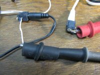
* The first two photos, 5445 and 5446 (mouse over the photos for their number, and remember you can click the arrows in the lower left of the photos to expand them) show the basic setup. The wall wart uses 5.5mm outer and 2.1mm inner barrel jacks, which happen to be the same ones used by the NwAvGuy O2 Headphone amp.
Like the Adadfruit write-up says, the black lead out of the supply is your "normal" positive lead, with tip positive polarity (the end contact on these jacks) and barrel negative. The white lead is the negative supply. Like the write-up says the tip of that one is also positive, and internally connected to the barrel of the positive supply to form the "real" ground between the two. The third contact on these jacks is an internal switch which isn't used here.
So essentially there are two normal supplies packed in the one wall wart here, just with the negative lead of one (the black wire) connected to the positive lead of the other (the white wire) to make a +/- supply with real ground in the middle.
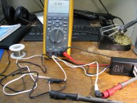
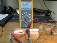
The first thing to do then is verify the supply really is wired this way. In the first photo, 5445, the meter is measuring continuity in the supply between the barrel of the black lead and tip of the white. Sure enough, a short. 0.69 ohms is the resistance of the meter leads, leads in the supply, and test clip contact resistance. So in this case 0.69R is a short. And, of course, the wall wart isn't powered up yet here.
* Next photo, 5449, shows the voltage on the positive half while unloaded. 12.24Vdc, just what we would expect. The negative (white lead) supply isn't shown but was similar.
* Next photo 5450 shows the "real ground" jumpered between the two jacks [EDIT oops, ran out of photo slots, had to remove this one to get it all in one posting]. Since this is also internally connected in the supply I could have skipped this step. But since we are doing noise analysis here made sense to also make the connection at the end of the long power supply cables.
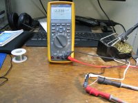
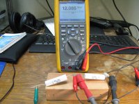
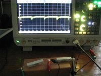
* Now things start to get fun in photos 5454 and 5455 with load resistors attached. Those are two 33 ohm 10W resistors. 12Vdc/33R = 0.36A = 360mA on each side of the wall wart. The supply is rated at 500mA so ideally these would be 24R resistors, but 33R is what I had on hand in the high wattage type. Close enough for our purposes here.
The photos show the loaded voltages on each supply half. Note still above 12Vdc even with the heavy load.
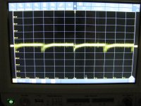
* The next two photos 5456 and 5457 show the scope connection across the positive supply load resistor and resulting waveform. OK, here it is, the switching noise! The horizontal on the scope here is 5uS/div, so the period is about 3 divisions or 15uS. 1/15uS = 67KHz. The vertical is 100mV/div, so around 100mV. I'm using a x10 probe here but the scope knows about it and has adjusted the scale to match. I haven't shown the waveform on the negative (white) lead (the other load resistor here), but I did take a look and it was similar.
As I wrote in the post above, these kind of numbers will usually work out fine for audio. In fact they do, see the audio analyzer results next.
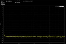
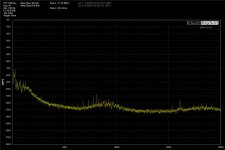
* Photo 5460 shows the connections to a QA401 audio analyzer, across the black lead load resistor (the photo is actually with the analyzer leads connected together, first screen shot, for background noise). The QA401 has built-in AC coupling and blocking to 54Vrms, so OK to just hook 'er up to the power supply here.
* In the final two screen captures from the QA401 the first is with the lead connected together to show background noise in the leads and analyzer, as a base reference. The second photo is across the black power supply lead load resistor. In both of these averaging is set to 10.
Well... pretty d*mn good, I would say! No major frequency spikes through the 20KHz audio band. The few lines that are there are tiny, 10dBFS or so. Note the scale on the left, all of this is wayy below the hearing threshold. Some of the noise floor rising from 5KHz to 0Hz (leftmost) is most likely due to environmental noise pickup in the room here (fluorescent lights with electronic ballasts).
In summary: good work, Adafruit, and WoodyLuvr in finding this product!
Here is the promised analysis of the nice +/-12V 500mA wall wart that WoodyLuvr found at Adafruit, their product ID 2591.
The summary is that it looks great for audio! Should be a real time-saver in powering some projects, like the Super CMOY here.* The first two photos, 5445 and 5446 (mouse over the photos for their number, and remember you can click the arrows in the lower left of the photos to expand them) show the basic setup. The wall wart uses 5.5mm outer and 2.1mm inner barrel jacks, which happen to be the same ones used by the NwAvGuy O2 Headphone amp.
Like the Adadfruit write-up says, the black lead out of the supply is your "normal" positive lead, with tip positive polarity (the end contact on these jacks) and barrel negative. The white lead is the negative supply. Like the write-up says the tip of that one is also positive, and internally connected to the barrel of the positive supply to form the "real" ground between the two. The third contact on these jacks is an internal switch which isn't used here.
So essentially there are two normal supplies packed in the one wall wart here, just with the negative lead of one (the black wire) connected to the positive lead of the other (the white wire) to make a +/- supply with real ground in the middle.
The first thing to do then is verify the supply really is wired this way.
In the first photo, 5445, the meter is measuring continuity in the supply between the barrel of the black lead and tip of the white. Sure enough, a short. 0.69 ohms is the resistance of the meter leads, leads in the supply, and test clip contact resistance. So in this case 0.69R is a short. And, of course, the wall wart isn't powered up yet here.* Next photo, 5449, shows the voltage on the positive half while unloaded. 12.24Vdc, just what we would expect. The negative (white lead) supply isn't shown but was similar.
* Next photo 5450 shows the "real ground" jumpered between the two jacks [EDIT oops, ran out of photo slots, had to remove this one to get it all in one posting]. Since this is also internally connected in the supply I could have skipped this step. But since we are doing noise analysis here made sense to also make the connection at the end of the long power supply cables.
* Now things start to get fun in photos 5454 and 5455 with load resistors attached.
Those are two 33 ohm 10W resistors. 12Vdc/33R = 0.36A = 360mA on each side of the wall wart. The supply is rated at 500mA so ideally these would be 24R resistors, but 33R is what I had on hand in the high wattage type. Close enough for our purposes here. The photos show the loaded voltages on each supply half. Note still above 12Vdc even with the heavy load.
* The next two photos 5456 and 5457 show the scope connection across the positive supply load resistor and resulting waveform. OK, here it is, the switching noise!
The horizontal on the scope here is 5uS/div, so the period is about 3 divisions or 15uS. 1/15uS = 67KHz. The vertical is 100mV/div, so around 100mV. I'm using a x10 probe here but the scope knows about it and has adjusted the scale to match. I haven't shown the waveform on the negative (white) lead (the other load resistor here), but I did take a look and it was similar.As I wrote in the post above, these kind of numbers will usually work out fine for audio. In fact they do, see the audio analyzer results next.
* Photo 5460 shows the connections to a QA401 audio analyzer, across the black lead load resistor (the photo is actually with the analyzer leads connected together, first screen shot, for background noise). The QA401 has built-in AC coupling and blocking to 54Vrms, so OK to just hook 'er up to the power supply here.
* In the final two screen captures from the QA401 the first is with the lead connected together to show background noise in the leads and analyzer, as a base reference. The second photo is across the black power supply lead load resistor. In both of these averaging is set to 10.
Well... pretty d*mn good, I would say!
No major frequency spikes through the 20KHz audio band. The few lines that are there are tiny, 10dBFS or so. Note the scale on the left, all of this is wayy below the hearing threshold. Some of the noise floor rising from 5KHz to 0Hz (leftmost) is most likely due to environmental noise pickup in the room here (fluorescent lights with electronic ballasts). In summary: good work, Adafruit, and WoodyLuvr in finding this product!
Attachments
-
 IMG_5445.JPG356.1 KB · Views: 99
 -
 IMG_5446.JPG285.7 KB · Views: 93
 -
 IMG_5449.JPG340.8 KB · Views: 75
 -
 IMG_5454.JPG321.1 KB · Views: 76
 -
 IMG_5455.JPG290.4 KB · Views: 70
 -
 IMG_5456.JPG255.4 KB · Views: 74
 -
 IMG_5457.JPG266 KB · Views: 77
 -
 IMG_5460.JPG336 KB · Views: 87
 -
 split supply analyzer grounded avg_10.jpg41.5 KB · Views: 93
 -
 split supply analyzer connected avg_10.jpg42.2 KB · Views: 79
Last edited:
- Home
- Amplifiers
- Headphone Systems
- OPA1688 Super CMOY, 2x 9V with real ground and headphone relay - PCBs